adsense analytic

Monday, April 30, 2018

Benefits of floating column

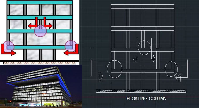
Floating Column or Hanging Columns: The floating column belongs to a vertical member that is laid on a beam and it doesn’t deliver the load directly to the foundation. The floating column operates as a point load on the beam and this beam transmits the load to the columns situated under it.

The column may set out on the first or second or any other midmost floor as resting on a beam. Generally, columns are laid the foundation to deliver load from slabs and beams. But the floating column is laid on the beam.

It signifies that the beam providing support to the column performs as a foundation. That beam is known as a transfer beam. This is extensively applied in high storied buildings for both commercial and residential purpose. It facilitates to customize and rectify the plan of the top floors. The transfer beam that provides support to the floating column, reassigns the loads up to foundation. For this reason, it should have been designed with more reinforcement.

Floating Column in Buildings: In recent times, multi-storey buildings are developed for the purpose of residential, commercial, industrial etc., containing an open ground storey. To provide space for parking, the ground storey is reserved free devoid of any constructions, exclusive of the columns which move the building weight to the ground.

For a hotel or commercial building, usually, there are banquet halls, conference rooms, lobbies, show rooms or parking areas in lower floor, hence large alternate space is necessary for the transition of people or vehicles. The columns which are narrowly placed in the upper floors, should not be located in the lower floors. Hence, to get rid of this issue, floating column concept becomes vital.

In urban areas, multi storey buildings are developed supported with floating columns at the ground floor for the different objectives. These buildings with floating columns are treated as secured under gravity loads and therefore are designed only for those loads. But these buildings are not suitable for earthquake loads and hence, these buildings are treated as insecure in seismic prone areas.

When the floating columns are arranged in buildings in seismic prone areas, the whole earthquake of the system is allocated with the column or the shear walls devoid of assessing any contribution from the floating columns.

Floating Column & Earthquake: The floating columns are useful for various projects specifically over the ground floor, where transfer girders are used with the purpose of providing more open space in the Ground Floor.

In the earthquake prone zones, the transfer girders which are applied should be designed and detailed correctly. If no lateral loads exist, the design and detailing work will not be complicated.

Concept of floating column primarily includes disrupting flow of transfer of EQ force.

• Floating columns must be designed as a normal compression member.
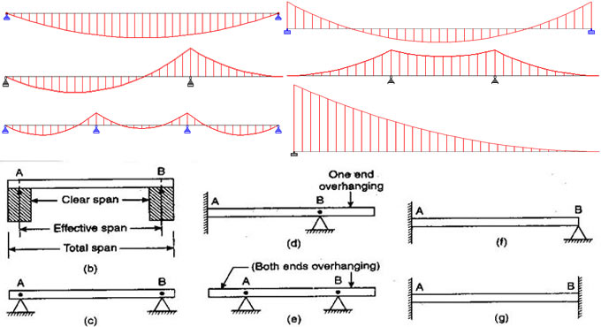
• At the time of designing transfer beam, it is designed as beam bearing all that load of column as a single point load.
• It should be remembered that EQ force developed should be reduced along the shortest path. It means load is dispersed between two intermediate columns which provide support to that beam.


High shear capacity beams/deep beams are utilized to provide support to the floating column. In some areas, the floating columns are inevitable. So, it is essential to alter code provisions for deep beams.

Article Source: engineeringcivil.org

Benefits of floating column

~~~~~~~~~~~~~~~~~~~~~~~~
Published By
Rajib Dey
www.constructioncost.co
~~~~~~~~~~~~~~~~~~~~~~~~

Friday, April 27, 2018

How verticality of structure is checked during construction

It is essential to verify the verticality while building up the construction at various phases like setting up vertical formworks of columns and transmitting levels up succeeding floors of multi storey structures.

Different types of processes are used to manage or verify verticality works throughout building construction which are explained below :-

The following processes are followed to verify or manage verticality works:

1. Plumb-Bob Technique: Plumb-bob comprises of a weight having pointed tip on the bottom connected with the end of a string. The heavy weight will suspend under gravity and provide a perfect vertical line that is known as plumb line.

This process is useful for examining or managing vertical line of structural elements specifically indoors like lift shaft. With the addition to that, it gets the ability to manage verticality of foundation, walls, and columns.

The wind force affects the plumb line or vertical line of plumb-bob and it’s perfectness can’t be retained. Small to medium lateral movement of plumb-bob can be decreased favorably by moistening it in oil or water.

If structural member’s height is extensive, then the string can be substituted with a long wire, but persistent cautions should be plasticized to get rid of imposing risks to the personals working below.

2. Spirit Level Method: This tool is very suitable for managing verticality of small scale works as for instance verifying formworks and door frames. If spirit level is applied for approximate checks, then it becomes essential to examine the verticality with more precise technique.

3. Theodolite Method: Theodolite is considerably robust instrument that can be utilized to verify the verticality works throughout construction by maintaining exactness and correctness.

It is undertaken for examining or managing verticality of towers, wall, foundation and columns; specifically huge number of columns along a one grid line.

The slope out of plumb line of the member can be calculated with Theodolite in conjunction with a tape.

The following methods are applied to examine the verticality of column:

a. Arranging the digital Theodolite to the center on a peg that installed 500 mm from the column grid.
b. Once set up is completed properly, the laser beam will be activated and concentrated it to the steel tape that is retained to the formwork.
c. Obtain the reading of the steel tape via the telescope.
d. Obtain the readings of two positions at the equivalent level on both top and bottom levels of the formwork. With two readings at the equivalent level, it will be possible to recognize any curvature on the surface.


4. Optical Plummet Method: It is a useful tool that sight directly down or directly up. There is an automatic compensator in optical plummet that enhances its precision drastically concerning other methods applied for managing verticality.

Article Sourcetheconstructor.org

How verticality of structure is checked during construction

~~~~~~~~~~~~~~~~~~~~~~~~
Published By
Rajib Dey
www.constructioncost.co
~~~~~~~~~~~~~~~~~~~~~~~~

Thursday, April 26, 2018

How beams are categorized on the basis of different factors

In structural engineering, various structural members are titled on the basis of their behavior under applied load. If the primary mode of delivering the load occurs due to bending then the structural member is known as beam. It can be also said that a beam belongs to a structural component that has the ability to resist load initially by making resistance against bending.

Beams usually bear vertical gravitational forces but can also be applied for bearing horizontal loads (e.g., loads originate because of an earthquake or wind). The loads which beam bear are transmitted to columns, walls, or girders and which then transfer the force to the adjoining structural members and lastly to the ground.

Categorization of Beam: Beams are distinguished with their support condition, profile (shape of cross-section),geometry, equilibrium condition, and their material.

Categorization on the basis of supports: Categorization of beams on the basis of support condition is essential since the bending moment functioning on the beam is directly influenced by the support condition. The difference can be seen in the bending moment diagrams given below. For the equivalent length and loading the bending moment diagram fluctuates significantly with change in support condition.

Simply supported – Beams are supported on the ends which can rotate easily without any moment resistance.

Fixed – Beams are supported on both ends and constrained from rotation.

Over hanging – Simple beams which are expanded beyond its support on one end.

Double overhanging – Simple beams with both ends extending beyond its supports on both ends.

Continuous – Beams are expanded over in excess of two supports.

Cantilever – A projecting beam that is fixed only at one end.

Trussed – A beam is reinforced with the inclusion of a cable or rod to develop a truss.

Categorization on the basis of profile: The type and magnitude of internal stress created in the beam is directly reliant on the shape of the cross-section, thus categorization is necessary on the basis of profile.

Rectangular Beams: I-Beams, T-Beams, C-Beams, Other Cross-sections

Categorization on the basis of geometry: The type and magnitude of internal stress created in the beam is also directly reliant on the geometry of the beam, thus categorization is necessary on the basis of geometry.

Straight Beams, Curved Beams, Tapered Beams

Categorization based on indeterminacy: The design of beam is mainly created for bending moment and shear force. Assessment of these bending moments and shear force is called analysis. A beam is classified into following two categories on the basis of the type of analysis necessary to work out the reaction:

Statically determinate beams: equilibrium conditions tolerable to compute reactions.e.g. simply supported beams, cantilever beams, single and double overhanging beams etc.

Statically indeterminate beams: Deflections (Compatibility conditions) together with equilibrium equations should have been applied to determine the reactions.e.g. propped cantilever, continuous beams, fixed beams.

Categorization on the basis of the material: Various materials contain different advantages and drawbacks for being utilized as a building material for erecting the beams concerning cost and usage, as a result beams are also classified on the basis of the material used for their construction.

Concrete Beams, Steel Beams, Timber Beams

How beams are categorized on the basis of different factors

Read more

~~~~~~~~~~~~~~~~~~~~~~~~
Published By
Rajib Dey
www.constructioncost.co
~~~~~~~~~~~~~~~~~~~~~~~~

Wednesday, April 25, 2018

Steps to work out road filling in hilly area

S.L. Khan, the eminent civil engineer, presents another informative construction video tutorial where he briefly explains the process for working out the road filling in hilly area.

In this video, solution is given to the following examples :-


Examaple 1


With specified cross section of road in hill area, work out the quantity of earth work in banking toward the length of 100 ft.


Suppose the permission rate of the road is taken as breadth of the road and it is 32 feet. The half of it is 16 feet. The mean depth of the filling is taken as 1.85 feet. The side slope is taken as 2:1. The cross slope is taken as 10:1.


Based on the above data, the quantity of earth work in banking will be determined.


To obtain the total filling of this section, apply the following formula :-


Filling = Cross Section Area x Length


To learn rest calculation process, go through the following video tutorial.


~~~~~~~~~~~~~~~~~~~~~~~~
Published By
Rajib Dey
www.constructioncost.co
~~~~~~~~~~~~~~~~~~~~~~~~

Tuesday, April 24, 2018

How to design any one way simply supported slab

In this construction video tutorial, you will learn how to create the design of one way slab (simply supported slab) that is standing on the masonry wall.


You will also gather information on all checks for making design of the slab.
The requirements and materials of the slab are given below :-
Clear span = 3m
Live load = 4000 N/m2
M20 concrete and fe 415 steel are used here.
The calculation is made on the following dimensions :-
A bearing of 120 mm is provided at each end. The distance among centers of bearing = 3+0.12 = 3.12 m
Necessary effective depth = Span/20 x modification factor
= 3120/20 x 1.40 = 112 mm
The bars with 8 mm diameter are arranged with clear cover of 15 mm.
Effective cover = 15 + 4 = 19 mm
Overall necessary depth = 112 + 19 = 131 mm
It is necessary to arrange an overall depth of 135 mm
So, effective depth = 135-19 = 116 mm
The Dead load of the slab will be calculated as follow :-
25 x 135 = 3375 N/m2 (floor finished with C20 mm).
Live load = 4000 N/m2
Therefore, total load = 7855 N/m2
Factor load = Wµ = 1.50 x 7855 = 11782.5 N/m2
To get more details, go through the following video tutorial.
How to design any one way simply supported slab

~~~~~~~~~~~~~~~~~~~~~~~~
Published By
Rajib Dey
www.constructioncost.co
~~~~~~~~~~~~~~~~~~~~~~~~

Monday, April 23, 2018

How to measure prying force in bolted connection

This is another useful construction tutorial from Dr. Chirag Patel. In this video, you will learn how to make detail measurement for "Prying Force" in bolted steel structural connection as well as remove it’s effect.

In a tension or hanger connection, the operative load creates tension in the bolts and the bolts are designed as tension members. If the connected plate is admissible to deform, supplementary tensile forces known as prying forces are developed in the bolts.

In this video example is given for verifying the exact capacity of a D hanger connection based on the following dimension :-
Bolt Diameter = 30 mm
Bolt Grade = 4.6
Dimension of end plate = 230 x 150 mm
Thickness of T-flange = 32 mm
The connection will not collapse if the tension capacity is higher than total load. Here, tension capacity is taken as 200 kN.
To learn the detail calculation process, go through the following video tutorial.
How to measure prying force in bolted connection+

~~~~~~~~~~~~~~~~~~~~~~~~
Published By
Rajib Dey
www.constructioncost.co
~~~~~~~~~~~~~~~~~~~~~~~~

Saturday, April 21, 2018

Waterproofing of Concrete, Walls and Floors

Construction of any building is not easy and it doesn’t end after completing the building; as there are so many other little things that need to look after before making a building.

One of those is waterproofing the building, a building must be guarded from water, heat, heavy sunrays and dust; if any of them is not properly followed during the construction then the building is not safe actually. Waterproofing is done at the time of concrete and sometimes a badly made concrete can’t guard the building from water for the discrimination of water by any admixtures.

A concrete is called waterproof when a dense concrete is made with right amount of total non-porous material and low water ratio; which will create a minimum of air blanks. As all concretes are porous so these holes need to be reduced for making the concrete so far tight to water.

It is sometime good to use a little extreme proportion of fines to make a good concrete; also a little increment in cement content over normal concrete is also beneficial as more cement needs less water for the same amount of work.

This thing need to describe a little more, here some methods is discussed for waterproofing:

a) Concrete and masonry grains are made waterproof with the use of three substitute layers of alum and soap mixtures, at first a hot alum solution is prepared with hot water, applied and worked in with a firm brush after pouring the hot soap mixture. The solutions are used with a gap of about 24 hours between the alternate coats; soap mixtures act like lubricants and also form difficult fillers by response with cement and may be applied while the concrete remains green.

b) When a fully hydrated white lime is added with the following mixtures it gives more proof from water; this mixture acts good as the lime paste absorbs about double the volume of paste when it mixed with equal weight of cement. It is also very effective in faulty filing but the mixture should be of thick concrete; the hydrated lime actually grows ability of work that gives a slight decrease in water content and reduces penetrability. Concrete must be made rich where the excess cement should be 15-20% over sand and 20% excess mortar over rough aggregate; a ratio mixture of 1:1.5:3 with water/cement ratio of about 0.40 will make the concrete really water-proof.

c) After the practicable work, the form-work has to be removed and the concrete exterior should be rubbed smooth and washed. To fill the holes, a mixture of cement and sand in the ratio of 1:1.5 with water-proofing compound is applied over the whole exterior without leaving any material on the concrete face.

d) Work on concrete floors are done at the time of cementing with dry cement which is sprayed over the exterior and worked in with a steel trowel on the first set of the concrete.

e) The method of water-proofing on the surfaces depend on the quality of concrete and the smallest holes can be filled with slit or fine clay, boiled linseed oil, paraffin or varnish then brushed over the exterior after the concrete has dried well. Nearly two or three layers are applied and dried before the next application; one or two layer of coal tar makes the exterior waterproof, concrete must be dry and free of dust and a thin bituminous coat can also be given for more firmness.

f) Generally Bituminous Putties are laid on horizontal exteriors and also mopped on vertical exteriors when they are either hot or cold.

g) Proprietary compounds like Pudlo, Medusa etc. are used as per the instructions of manufacturers. Insert materials which are of the finest particles can be used to dense the concrete especially when the total is in fines.

h) Silicate or soda also works well in water-proofing; whereas the mixture of 1 kg of washing soda and water will make a cement mortar water-proof.

For more information, go through the following construction article theconstructioncivil.org

Waterproofing of Concrete, Walls and Floors

~~~~~~~~~~~~~~~~~~~~~~~~
Published By
Rajib Dey
www.constructioncost.co
~~~~~~~~~~~~~~~~~~~~~~~~

Friday, April 20, 2018

The benefits of steel buildings in construction industries

Steel buildings are mostly recognized since they are inexpensive as well as they can be mass produced and adapted from prevailing standards to fulfill various purposes.

The uses of steel building are found in different sectors like agricultural to commercial.

ADVANTAGES OF STEEL BUILDINGS

1. They are cost effective as compared to other building materials since you don’t have to appoint the engineers and architects for constructing the building. The steel buildings can be easily sustained and can be mass produced. They are one of the affordable types of building obtainable at this level.

2. Steel buildings are perfect for almost any space, specifically as they fulfil the needs for various types of single story buildings. They are also greatly ecological, specifically when provided with thermal accessories – of which several types are well-suited – for increased energy efficiency.

3. They can be sustained efficiently. In wooden buildings, or any type of structure which are built with organic material, there is chance for mould and mildew infestations and steel buildings are 100% eco-friendly so can either be easily reprocessed.

4. Steel buildings are utilized for different purposes: agricultural, storage, offices, temporary venues etc. They can be built up easily secure, both from damage and outside access, since steel (not like wood) will not distort and fastenings will persist protected in due course of time.

5. Steel buildings can be constructed easily and maintainable by their users, and be associated with a variety of supplementary features which can be acquired at little additional cost from the manufacturer. These extra features contain mezzanine options, green energy solutions, additional access doors and colors.

6. Steel buildings are designed for both permanence and impermanence that means they can be utilized for stockpile throughout project accomplishment or for long term stockpile of machinery or goods. Besides, the steel building are environment friendly as they can be easily set up with solar panels.

The benefits of steel buildings in construction industries

Read more

~~~~~~~~~~~~~~~~~~~~~~~~
Published By
Rajib Dey
www.constructioncost.co
~~~~~~~~~~~~~~~~~~~~~~~~

Tuesday, April 17, 2018

Variations among pier, abutment and column

This construction video tutorial sheds light on the variations among pier, abutment and column. It is a very important topic for civil engineering students.

Definition of Pier: Normally, pier stands for the types of column which are situated among the two abutments in the bridge to accommodate the load of super structure of the bridge.

It transmits the load of vehicles, slab and longitudinal and cross beams to the foundation.

Definition of Abutment: It is mainly applied at the ends of the bridge to keep hold of the embankment as well as bear the vertical and horizontal loads for the bridge super structure to the foundation. Abutments are normally built up from concrete to combat the heavy load of the vehicles.

Abutment and pier have to resist wind and seismic load other than the load transmitted to it from beams and are known as substructure of bridge.

Definition of column: In Civil Engineering term, the column refers to a vertical member that bears the compressive load as well as transmits the load from slab and beams to the Foundation or Footing.

Variations among Pier and Abutment

Piers belong to the internal supports of the bridge.

Abutments belong to the ends supports of the bridge.

Abutment is developed in the end of bridge to support vertical and lateral moments, whereas, if we have a bridge containing multi spans, then, pier is arranged in the end of each span to support the same forces and moments.

More than two piers can be used in bridge construction.

The numbers of abutments are just two in the bridge at the ends.

Piers are built up among the abutments.

Abutments are the external support of the bridge.

To get more details go through the following video tutorial.


~~~~~~~~~~~~~~~~~~~~~~~~
Published By
Rajib Dey
www.constructioncost.co
~~~~~~~~~~~~~~~~~~~~~~~~

Monday, April 16, 2018

The role of water in concrete

Water Cement Ratio signifies the ratio among the weight of water to the weight of cement applied in concrete mix.

Generally, water cement ratio remains under 0.4 to 0.6 with adherence to IS Code 10262 (2009) for nominal mix (M10, M15 …. M25)

The strength of concrete is directly impacted by the water cement ratio. It enhances the strength if employed in perfect ratio and if the ratio is improper, the strength will be reduced.

The importance of Water in Concrete

Concrete refers to a macro content. It comprises of micro constituents like cement, sand, fine aggregate & Coarse aggregate. With the purpose of obtaining high strength concrete to resist the desired compressive strength, it is required to set exact ratio of admixture to unite these materials.

The role of water is important here to accelerate this chemical process by adding 23%-25% of the cement volume. It produces 15% of water cement paste also called gel to fill the voids in the concrete.

Impact of too much water in concrete: If additional water is added more than the permissible limit of 23%, the strength of concrete will be significantly affected.

If the task of adding water is continued to improve the workability then the concrete contains lots of fluid materials where the aggregates will settle down. As soon as the water is evaporated it puts down lots of voids in concrete which influences the concrete strength.

But if the guidelines are followed to retain the strength of the concrete then it will change the concrete workability and makes it difficult to manage and place them.

Workability signifies the capacity of concrete to manage, convey and place devoid of any segregation. The concrete becomes perfectly workable if it can be easily dealt with, placed and transported devoid of any segregation at the time of being placed in construction site.


For this purpose, plasticisers & superplasticizers are utilized to enhance the workability by keeping the W/C Ratio unchanged.
In order to know how to work out water cement ratio, go through the following construction article www.civilology.com
The role of water in concrete

~~~~~~~~~~~~~~~~~~~~~~~~
Published By
Rajib Dey
www.constructioncost.co
~~~~~~~~~~~~~~~~~~~~~~~~

Friday, April 13, 2018

The detailed method of highway construction

By making extensive surveys and subgrade groundwork, highway construction is normally conducted. The methods and technology for constructing highways are upgraded in due course of time and turns to be more advanced.

The improvement in technology has increased the grade of skill sets essential for dealing with highway construction projects.

This skill differs from project to project, on the basis of different factors like the project’s complications and type, the contrasts among new construction and reconstruction, and variations among urban region and rural region projects.

There exist various components of highway construction which are segregated into technical and commercial components of the system. Given below, some illustrations of them:

Technical Components -

a. Materials
b. Material quality
c. Installation systems
d. Traffic


Commercial Components -

a. Contract understanding
b. Ecological characteristics
c. Political characteristics
d. Legal characteristics
e. Public interests


Generally, construction starts at the lowermost elevation of the site, in spite of the project type, and moves upward. After evaluation of the geotechnical specifications of the project, the following information is provided:

Present ground conditions -

a. Necessary apparatus for excavation, grading, and material transportation to and from the site
b. Characteristics of materials to be excavated
c. Necessity of dewatering for below-grade work

d. Necessity of shoring for excavation protection
e. The quantities of water for compaction and dust control


The detailed method of highway construction

Read more

~~~~~~~~~~~~~~~~~~~~~~~~
Published By
Rajib Dey
www.constructioncost.co
~~~~~~~~~~~~~~~~~~~~~~~~

Thursday, April 12, 2018

Quantity Surveyor with Autodesk Quantity Takeoff Skills Salary in India

QTO or Quantity take-offs is a thorough estimation of materials and labors which are required to complete any construction project.

These QTOs are expanded by an estimator in the preconstruction time and the estimation is used to format a bid on the range of construction.

Job Description: It is known to all that most of the engineering and construction projects come with large-scale actions and they need the investments of large amount of money. Projects are often get form some clients or contractors who want the highest quality in the project with a minimal cost that’s why they engage people called quantity surveyors. So basically a quantity surveyor has to do the job of a financial manager for a large engineering project who is charged with the maximum value of the project for his/her client to give a right balance of cost and quality.

When a quantity surveyor is involved in a project, he/she has to work with clients and their contacts from the start of the project during the process of the contract and engaging in opening cost analysis. From the start to end of a project, a quantity surveyor has to keep a continuous observation over the whole process and finds way for more improvement in the investment and project by producing daily profitability reports and keeping all the updates. Besides that, quantity surveyors also give advice and support for different tasks pursuing completion of the project for further changes.

Qualification: A quantity surveyor should have a college degree with significance in engineering and/or finance. So candidates must have to pursue official certificate and those who are not form a technical surveying will not be eligible so necessary education and experience is needed.

Wages: A Quantity Surveyor with the skills of Autodesk Quantity Takeoff can get the average payment of Rs. 418829 per year and the job needs a strong experience though this job generally don’t have more than 20 years’ experience. Salary could be Rs. 201164 – Rs. 833129 and bonus will vary that can be up to Rs. 95449 and with that there is also be the profit sharing, so it is clear that a quantity surveyor can get a good salary.

Quantity Surveyor Tasks:
• A quantity surveyor has to help in the credentials of commercial risks and chances and execute value engineering exercises when it is needed.
• He/she has to make and control material provision schedules.
• A quantity surveyor has to stimulate and develop a culture of contract awareness and assure about the fulfillment of contracts by stiffly maintaining records, contractual notifications, changing control etc.
• Also need to ready internal value reports for upper management and other departments.
More than that, they can get jobs in their cities or their nearby cities so start finding.
Apply Online www.payscale.com
Quantity Surveyor with Autodesk Quantity Takeoff Skills Salary in India
~~~~~~~~~~~~~~~~~~~~~~~~
Published By
Rajib Dey
www.constructioncost.co
~~~~~~~~~~~~~~~~~~~~~~~~

Wednesday, April 11, 2018

Testing of Concrete masonry Blocks

Concrete masonry bricks are very useful in the rural areas as it is cheap, easily found and can form less strong buildings, the compressive strength of the bricks should be tested.

And in urban areas these kinds of buildings may present a combination of both office and houses or grocery stores and houses or offices and retail stores.

Concrete can be changed into formed masonry units like Hollow and Solid normal and light weight concrete blocks in right size to use for load and non-load bearing units for fencings or wallings. These concrete blocks are used more in the regions where soil bricks are costly, have less strength and not available all the time. As per the structural needs of masonry unit, the concrete mixes can be arranged using available ingredients or if not be suitable then with in the most economical distance.

Hollow concrete blocks are used for normal masonry when reinforced is used and it should not be leaner than 1 part cement of 8 parts room dry sand by volume. Compressive strength of concrete blocks or concrete masonry units is important to know the fitness of these in construction works for different reasons. Concrete masonry blocks are normally made of cement, amount and water which are usually comes in rectangular shape used in construction of masonry structure.

Patterns

20 full sized units shall be counted for length, wide and height and the center units shall be calculated for least thickness of face, shells and webs.

The minimal dimensions of concrete masonry block differ in three things such as:

  • Length: 400/500/600mm
  • Width: 200/100mm
  • Height: 50, 75, 100, 150, 200 or 300mm.

Tests on Concrete Masonry Block Units

various tests are done on concrete masonry unit to check all the requirements, but among them three most applied tests are discussed in this article. The blocks of same mix shall be taken and classified to these following tests:

  • Dimension measurement for all types of blocks
In this step all the blocks should be verified and calculated by the length, width and height with steel scale. After checking if the block found hollow, then the thickness of the web and face shell are calculated with caliper ruler, next a report need to be prepared included average length, width and height of block and with least face shell and web thickness using recorded dimensions.

  • Density of the concrete masonry blocks (3 blocks)
At first the block has to be heated in the oven to 100°c, then the heated block need to be cooled in the room temperature. Next measure the dimensions of block to find out the volume and weight of it, the density of the block is calculated form a calculation and the standard density of 3 blocks will be the final block density. The formula is: mass/volume (kg/m3 )

  • Compressive Strength tests
the average compressive strength of concrete masonry block is calculated by taking 8 blocks and all of them should be tested with in 3days after gathered in lab where the age of the blocks should be 28 days. The compressive strength is calculated in the Compressive

Strength Testing machine which has tow steel bearing blocks, one is in fixed position on which the masonry unit is kept and the other movable one can transfer the load to the masonry unit while applying. When the masonry unit’s bearing area is more than the steel blocks’ bearing area some different steel plates will be used. Those plates are organized on steel blocks in a way that the centre of masonry unit agreed with the center of thrust of blocks, bearing area units are completed with the Sulphur and granular materials coating. Then the unit in testing machine is placed and one-half of the expected highest loads are followed at a minimum rate while the rest is applied in not less than 2 minutes. Te load of masonry unit fails and the highest load is divided by basic sectional area of unit will give the compressive strength of block. By applying the same method, find out the rest 7 blocks’ compressive strength and then calculate the average strength of the 8 blocks which will be the final compressive strength of concrete masonry unit.


Some Commercial Building techniques that changing Construction

~~~~~~~~~~~~~~~~~~~~~~~~
Published By
Rajib Dey
www.constructioncost.co
~~~~~~~~~~~~~~~~~~~~~~~~

Monday, April 9, 2018

Steel Beam Connections

Steel beam connections are used to join different members of structural steel frame work; Steel Structure Collections attach various members to make them a unit.

Steel connections

Connections are like the structural elements which are used to connect various members of structural steel frame work and Steel Structure is a collection of different member like Beams, Columns which are joined with one another at member ends fasteners to show a single composite unit.

Types

Generally steel beam connections are used in structures and all beam connections are categorized into two groups like framed and seated connections. The framed steel beam is connected to the supportive steel element by fittings and the seated steel beam is placed on seat like to the case where beam is located on masonry walls.
This article mainly focuses on the different types of steel beam connections with their working process, steel beam connections are divided into following types:

  • Bolted Seated Steel Beam Connection
When a beam is joined with a support, a column or a girder with web connection angles, then the joint is names as ‘framed’. Here every the connections must be plotted for the end reaction of the beam, its type, size and toughness of the fasteners and the capacity of bearing strength of core materials should be done. In these connections, the steel beams are connected in a way as supporting elements whether it is steel columns with the web connection angles and the minimum length of connection angle must be at least half of the beam clear web depth. The proportion is specified for right stiffness and solidity; there are different sizes of bolted framed connections besides their capability given by codes. This connection is required to enhance the rapidity of the design and minimum connection is enough to resist the applied load for making the design more economical.

  • Bolted Framed steel connections
In seated connection beams right sizes, capabilities and other data are filed in the AISC Manual, there are mainly two main types of bolted seated connections one of them is the soft bolted seat connections and hard bolted seat connection. When the reactions at the end of the beam are big then it is approved as hard or stiffened seat connections for their satisfactory capacity to oppose large forces. But the capability of soft or unstiffened seat connection is blocked for limited bending capacity of seat angle leg. The most helpful thing is that the beam in this connection can be invented economically and seat would give immediate support in the erection period.

  • Welded framed steel beam connection

This beam connection can be found in different sizes with their capabilities are available and supplied by codes. The weld of connection is bound to direct shave stress which caused by loads on the beam which beam affect weld pattern so the stresses are needed to be considered. The part of the welding is executed in a field where it seems difficult to get high quality weld for the movements of steel members caused by winds or other factors.

  • Welded seat steel beam connection
It is same as to bolt seat connection but used for bonding than bolts and the pressure on the beams affect the weld pattern curiously and create stress which need to be planned. The welded seat connections are of two types: unstiffened and stiffened, unstiffened is used for small loads and the stiffened is used to bear large loads. Use bolts to connect beam bottom border to the seat and the blots can be removed at their position after the end of their welded process. This connection is not requested from environmental point of view and worker as the connection can’t be erected easily.

  • End plate steel beam connection
This kind of connection is made through using the welding art and the end plate is joined to the beam by weld for its capability and size which are controlled by shear capacity of the beam web connected with the weld. The applied load on the connection at last of the member doesn’t have irregularities and the plate connections are of various types like flexible, semi-rigid and rigid. The fabrications and cuttings must be connected with the extreme care to stop errors but the end plate connections are not applicable to tall steel structures.

  • Special steel beam connections
These connections are used for the case where the preparations of the structural element are placed in a way that standard connections can’t be used. The connections can transfer moments into the columns as per degree of fixity of the connections and the higher degree of fixity of the beam connection is the greater ability to transfer the moments into the columns.

  • Simple, rigid and semi-rigid connections
Moment connections can transfer the forces in the beam sides to the column and this transfer moment must be provided for more and usually free of the shear connection needed to support the beam reaction. Simple, rigid and semi-rigid connections are designated simply to support beams and columns for shear only and leave the ends free to move under load. Besides carrying shear they provide enough rigidity to hold virtually unchanged angles between connected members.


Steel Beam Connections

~~~~~~~~~~~~~~~~~~~~~~~~
Published By
Rajib Dey
www.constructioncost.co
~~~~~~~~~~~~~~~~~~~~~~~~