adsense analytic

Friday, June 30, 2017

Variations among Warren Truss, Howe Truss and Pratt Truss

In engineering, a truss belongs to a structure that contains two-force members only. The members are arranged in order that the truss can act like a single object. The truss facilitates the structures to transmit weight to its foundations and anchors securely.
The members of truss are only dependent on axial compression and tension and not on bending moment.
The truss employs a web of triangles which are attached in order that pressure and tension are used to the points of the corners of every triangle to make them stable for providing support to structure. By associating a wide array of trusses collectively, significant amount of weight can be transmitted securely to load-bearing beams, wall or to the ground directly.

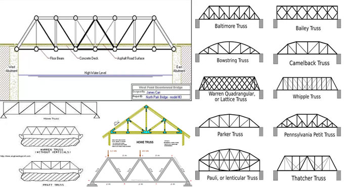
Generally, the trusses are categories as Warren truss, Pratt truss and Howe truss.
Warren truss is supported with a set of isosceles triangles or equilateral triangles. The verticals are included with Warren Truss with the purpose of raising the span length of the truss bridge.
Pratt truss is defined by its diagonal members (excluding the end diagonals) which are sloped down towards the middle of the bridge span. This type of structural arrangement is based on when external loads tension is caused in diagonal members whereas the vertical members manage compressive forces. Therefore, thinner and lighter steel or iron is applied as materials for diagonal members with the purpose of building up a more well-organized structure.


The design of Howe truss is contrary to that of Pratt truss in which the diagonal members are sloped in the direction contradictory to that of Pratt truss (i.e. slanting away from the middle of bridge span) and as such compressive forces are formed in diagonal members. Therefore, it is not cost-effective to employ steel members to deal with compressive force.

Variations among Warren Truss, Howe Truss and Pratt Truss


~~~~~~~~~~~~~~~~~~~~~~~~
Published By
Rajib Dey
www.constructioncost.co
~~~~~~~~~~~~~~~~~~~~~~~~

How to design the reinforced concrete wall

You have to design the Reinforced concrete wall similar to a compression member. Reinforced concrete wall is suitable when there are no beams and load transmitted from the slab is massive or the density of the masonry wall is restrained.
RCC Wall is segregated as follow:
• Plain concrete wall, when rein. < 0.4%
• Reinforced concrete wall, when rein. > 0.4%

Load from slab is transmitted as axial load to wall. When depth is greater, it is known as RC wall. Design is identical to a RC column, breadth is similar to the density of wall and depth is equivalent to 1m. The design of RCC Wall is based on the following factors.
• Axially loaded wall
• Axially loaded with uniaxial bending
Categorization of concrete walls:
1. Plain concrete wall
2. Reinforced concrete wall
Under plain concrete wall, the reinforcement included is under 0.4% of c/s. In reinforced concrete wall, the proportion of employed steel is in excess of 0.4% and is designed in the same way as reinforced concrete columns. Slenderness ratio is equivalent to minimum of (l/t or h/t), where, l denotes effective length of wall, h stands for effective height of wall, t stands for thickness of wall. When < 12, the wall becomes short and if > 12, the wall becomes slender.
Braced and Unbraced Concrete Walls:
Braced: If cross walls are arranged for the walls so as to they can bear lateral load and 2.5% of vertical load, then the wall is defined as braced. If not, the wall is called as unbraced wall.
Note: Other walls under special cases are,
i) Cantilever wall
ii) Shear walls – To withstand lateral loads [Handle flexure created because of lateral loading on the structure, depth is allowed along the transverse direction]


To learn the detail process, watch the following link theconstructor.orgn

How to design the reinforced concrete wall


~~~~~~~~~~~~~~~~~~~~~~~~
Published By
Rajib Dey
www.constructioncost.co
~~~~~~~~~~~~~~~~~~~~~~~~

Wednesday, June 28, 2017

Michael R. Penn and Philip Parker have published an exclusive book alias Introduction To Infrastructure

Both Michael R. Penn and Philip Parker have written an exclusive book alias Introduction to Infrastructure. The book is available in paperback version.
The book is specifically designed for civil and environmental engineering. The book sheds light on various facets of civil engineering that demonstrates interconnection of the various civil engineering fields. This 1st Edition focuses on an extensive range of engineering fields, as well as introduction to ethics.
Customary technical topics (as for instance - construction, environmental/water resources, geotechnical, etc.) are explained briefly through the text and in spite of discussing these sub-disciplines on a chapter–by–chapter basis, case studies are utilized to highlight their interconnection.
The text also highlights usages of civil and environmental engineering in practical, containing level of technical rigor (e.g. rudimentary); a conversational tone, motivating the reader; problem–based; and website associated text like existing news related to infrastructure; and ordinances (parking, stormwater, etc.) from communities of different sizes and geographic locations to be applied as the foundation for textbook exercises.

To purchase the book, click on the following link www.amazon.in

Michael R. Penn and Philip Parker have published an exclusive book alias Introduction To Infrastructure


~~~~~~~~~~~~~~~~~~~~~~~~
Published By
Rajib Dey
www.constructioncost.co
~~~~~~~~~~~~~~~~~~~~~~~~

Tuesday, June 27, 2017

Learn to compute cement quota, brickwork volume & no. of fixes for a brick wall

This construction video tutorial will show the details of cement quota, brick work volume, number of fixes for a brick wall construction.
To calculate the brickwork volume, just apply the following formula :-
Total brickwork area x wall thickness
= 31.98 x 0.2 = 6.38 m3

The ratio of cement & mortar needed in brickwork is 1:3 (it can also be taken as 1:5 and 1:6).
Volume of brickwork = 6.38 m3
For 1 cubic meter of cement mortar, the volume of sand will be 0.2m3
For 6.38 cubic meter, the volume of sand will be 6.38 x 0.2 = 1.276 m3
For 1m3 cement mortar, the volume of cement will be = (0.2x1440)/3 (3 denotes last digit of ratio)
= (0.2 x 1440)/3 = 96 KGS
For 6.38 cubic meter, the volume of cement will be 6.38 x 96 = 612.48 KGS
To work out the number of cement bags, just divide it by 50 (as weight of 1 cement bag is similar to 50 Kg)
Therefore, 612.48/50 = 12.24 bags = 13 bags (approx.)


Read more

~~~~~~~~~~~~~~~~~~~~~~~~
Published By
Rajib Dey
www.constructioncost.co

~~~~~~~~~~~~~~~~~~~~~~~~

Monday, June 26, 2017

Definition of striking and pointing in brickwork

The variation among 'striking' and 'pointing' is given below :-
• Striking stands for completing the mortar joints among the bricks which are placed freshly.
• Pointing means employing a small amount of mortar into the face joint among bricks (either freshly placed or in old brickwork). In new brickwork, harder mortar is used in pointing to enhance weather protection on uncovered faces. In old brickwork, pointing is frequently applied for fixing up mortar joints which are worn by exposition to the elements.

Styles of finishing - Either striking or pointing, the elementary finishes remain the similar:
FLUSHED: It is very complicated to provide flush finishing because of the deformities of maximum mass produced bricks.
It can be obtained by drawing a strip of wood having dimension 12mm wide, 6mm thick and 100mm long along the joints as soon as the mortar has begun to run off.
This is possibly the simplest finish for a new diyer to attain.
WEATHERED: Weathered finishing emits rain water and is treated as relatively long-lasting but it is difficult for a diyer to achieve a good finish.
The joint is prepared by drawing the blade of a small trowel, sloping marginally inwards at the top, backwards along the joint, the top edge of the trowel start joining the bottom of the bricks over the joint being struck.
Toward vertical joints, the edge of the trowel is connected with one of the side bricks and is disposed by the similar amount like the horizontal joint. Maintain the direction of the vertical strikes identical all over a wall, or else it may appear odd.
HOLLOW KEY: Hollow key – It is built up by dragging a proper curved or round shaped piece of metal (i.e. tube or rod) along the joints.
STRUCK: Struck jointing is not recommended for exterior facings because it keeps the top most edge of the lower brick uncovered to the weather.
The actual method is equivalent to the weathered finish above, apart from that the trowel is angled inwards at the lowermost of each horizontal joint.
Definition of striking and pointing in brickwork
~~~~~~~~~~~~~~~~~~~~~~~~
Published By
Rajib Dey
www.constructioncost.co
~~~~~~~~~~~~~~~~~~~~~~~~

Friday, June 23, 2017

Different types of clear cover in reinforcement concrete

This construction video tutorial provides brief instructions on how to arrange clear cover in different areas in proper quantities in reinforcement concrete. It is dependent on the exposure condition and fire resistance.
Clear Cover stands for the minimum distance among the surface of embedded reinforcement and the exterior surface of the concrete (ACI 130). The depth of clear cover is calculated with a cover meter.
Given below the details of clear cover :-
For water retaining structures – The clear cover should vary from 20 mm to 30 mm
For flat slab – The clear cover should be 20 mm
For slab – The clear cover will be 15 mm
For column – The clear cover should have been 40 mm
For strap beam – The clear cover should be 50 mm

For raft foundation at bottom – The clear cover should be 75 mm
For shear wall – The clear cover should be 25 mm
For footing – The clear cover should be 50 mm
For staircase – The clear cover should be 15 mm


Read more

~~~~~~~~~~~~~~~~~~~~~~~~
Published By
Rajib Dey
www.constructioncost.co

~~~~~~~~~~~~~~~~~~~~~~~~


Thursday, June 22, 2017

Necessary IS Codes for Functional Requirements In Buildings

A building code (alias building control or building regulations) stands for a series of rules which indicate the standards for constructed objects like buildings and nonbuilding structures. Buildings should abide by the codes to acquire planning permission, generally from a local council. The primary objective of building codes is to safeguard public health, safety and general welfare because they are associated with the construction and occupancy of buildings and structures.

Building codes are generally intended to be applied by architects, engineers, interior designers, constructors and regulators but are also used for various purposes by safety inspectors, environmental scientists, real estate developers, subcontractors, manufacturers of building products and materials, insurance companies, facility managers, tenants, and others. Codes regulating the design and construction of structures where adopted into law.

Given below, the detailed lists of all Indian Standard Codes which comprise of standardization in the area of functional requirements in buildings ranging from comfort point of view, for example space distribution, orientation, day-lighting, ventilation, acoustics and thermal comforts, from health and safety point of view, from the point of view of accessibility for persons with disability and from the point of view of energy requirements.

IS 1950:1962 Code of practice for sound insulation of non-industrial buildings
IS 2440:1975 Guide for day lighting of buildings
IS 2526:1963 Code of practice for acoustical design of auditoriums and conference halls
IS 3103:1975 Code of practice for industrial ventilation
IS 3362:1977 Code of practice for natural ventilation of residential buildings


IS 3483:1965 Code of practice for noise reduction in industrial buildings
IS 3792:1978 Guide for heat insulation of non industrial buildings

Necessary IS Codes for Functional Requirements In Buildings


~~~~~~~~~~~~~~~~~~~~~~~~
Published By
Rajib Dey
www.constructioncost.co
~~~~~~~~~~~~~~~~~~~~~~~~

Wednesday, June 21, 2017

Some useful guidelines on Vastu for a Living Room

The Vastu for Living Room provides a series of fundamental rules and if these rules are pursued properly, you along with your family can live problem free life in the Living Room. It is very crucial to keep the face of the living room to the East or the North direction. It is recommended to keep the face of your living room to the North as it will bring more prosperity. Toward North faced room, remember that the room should be larger in size with regard to the rest rooms of your house facing other directions but the height of the room should be little short.
In Living Room Vastu Shastra, the drawings, patterns and designs are dependent on the arrangements with the directions known as North, South, East and West. Living Room Vastu Shastra is mostly utilized over the ages on Hindu architecture and also in other arenas like vehicles, furniture, sculpture, paintings, so on.
Living Room Vastu placement: Beside maintaining face of the room to the proper direction, Vastu for living room also suggests to keep the slope of its flooring towards the North or the East. Regarding the doors, the eastern and the western doors are treated very sacred for your living room. The decorative items which are situated inside, particularly the heavy materials like the show case and all, should be arranged in the West or the South direction.
Vastu for living room also describes that the sitting position of the head of the family should have been in the North or the East. It is recommended not to arrange the television set to the North-east or the South-west rather it’s face should be directed to South-east. The telephone set should be kept either in the North or the East or the South-East direction. It is also suggested that the statues or portraits of Gods and goddesses should be arranged in the North-east corner. If any stuff of animal hide or skin is arranged on the walls, it should be hanging on the North-west walls.
Colors on Wall as per Vastu: Vastu for living room also reveals a vital factor about the color of the walls. Try to circumvent employing red or black for the walls. Painting on it should be done with colors like blue, yellow, white or green. Arrange the fanciful chandelier slightly to the West side of the room and it shouldn’t be positioned at the center. The shape of the furniture should be as much as possible square or rectangle and not circular, oval, hexagonal or shaped like an egg.
Some useful guidelines on Vastu for a Living Room

~~~~~~~~~~~~~~~~~~~~~~~~
Published By
Rajib Dey
www.constructioncost.co
~~~~~~~~~~~~~~~~~~~~~~~~

Tuesday, June 20, 2017

Benefits of Concrete floor heating

Reason For Floor Heating: Concrete floor heating is carried out by employing the high thermal mass concerning a concrete slab or floor with preservation of heat in the floor and it performs similar to a large heating panel, to heat the interior space over it and arrange a convenient living surroundings for the occupants.

The hot floor heats the whole space over it and is mostly suitable for finishes like polished concrete floors. Due to its radian output, the concrete floor that has been heated is capable of attaining convenient living conditions at a lower air temperature as compared to normal air heating systems. It is considered as one of the easiest forms of space heating that offers consistent, discreet heat.

The electric constituents or pipes that distribute hot water (called as hydronic systems) are implanted inside the concrete slab or topping screed to heat the concrete slab. Off-peak domestic heating tariffs may also be cost-effective to the homeowner when the energy source remains electricity for either type of system.


Preferably, employing concrete floors for heating is considered as most perfect to the buildings of solid construction where exterior and interior walls also contain a high thermal mass like concrete panel, brick or block walls. These materials, along with the concrete floor function as a heat bank or reservoir which preserve the heat. The method can also be fruitful in buildings of lighter construction along with brick veneer subject to some concern is given to sufficient insulation.


Read more

~~~~~~~~~~~~~~~~~~~~~~~~
Published By
Rajib Dey
www.constructioncost.co

~~~~~~~~~~~~~~~~~~~~~~~~

Monday, June 19, 2017

How to develop marble flooring in a site

This construction video tutorial provides step-by-step methods for arranging marble flooring properly.
The process involve the following steps :-
Initial step should be chipping floor slightly, The next step is to clean the area properly after chipping is completed, Again start chipping in major way, Spreading slurry of cement for affixing in a perfect manner, Start for the formation of mortar bed, Take out fibre from back side of marble, Cut mortar in such a manner in order that cement slurry can enter inside perfectly, Apply white cement slurry for Italian marble, Cleanse the edge of marble, Position marble properly, Check to maintain the exact level of flooring, Start to polish marble manually or through machine, Pros and Cons of Marble Flooring.

Benefits of Marble
• Marble produces a very glorious appealing look on the interiors specifically Italian marble.
• Marble flooring has good longevity. It is made of a heavy stone and can bear heavy loads on it.
• Marble flooring contains good resistance capacity against scratch.

Disadvantages of Marble
• The appropriate care and maintenance should be taken for marble. Acid should not be applied on marble as it’s shine will get lost. Marble should be polished frequently over a period of time to maintain it’s new look. Without proper cares, the marble turns out to be yellowish in color.
• Italian marble is normally very soft and there are chances for being cracked. Proper resins should be applied for getting a durable & solid surface and resisting of cracks.


• Exact sealants should be employed in marble flooring as the marble is extremely porous and likely to staining. It consumes stains rapidly especially kitchen stains henceforth are not suitable for kitchen counter tops.
• Marble is very heavy and several labor is needed for lifting purpose. Only very professional contractors have the ability to deal with marble flooring and insert design infill’s in the floor.
• Marble flooring is not recommended in winters as it gets severely cold


Read more

~~~~~~~~~~~~~~~~~~~~~~~~
Published By
Rajib Dey
www.constructioncost.co

~~~~~~~~~~~~~~~~~~~~~~~~

Saturday, June 17, 2017

ConSteel – A powerful structural Analysis software for steel & composite structures

ConSteel Solutions has developed ConSteel with the support of some renowned structural scientists, engineers and programmers. It is a powerful software for analyzing any structure efficiently. It is primarily used for the construction of steel and composite structures.
It is suitable for all the stages of the design process ranging from modeling; integrated analysis and standard design; brief inspection of cross-sections and structural joints; flexible documentation. For the purpose of making analysis and design, ConSteel employs the latest techniques concerning the modern structural standards which deal with the 3D structural model as a whole throughout the entire process. The user-friendly interface among ConSteel and Tekla Structures, ConSteel and StruCad facilitates the user to export the full designed model together with the placed joints and considerably minimize the detailing costs.
The most updated version is ConSteel 11 that provides efficient analysis and design solution for structural engineers with significant enhancements for collaboration.
The restructured seismic analysis tool creates huge scopes for structural engineers to accomplish apparent and overall seismic calculation. The completely new csPI interface makes the structural modeling process more improved.

A 30-dasy free trial version is available for the users. Just click on the following link to download the trial version www.consteelsoftware.com

ConSteel – A powerful structural Analysis software for steel & composite structures


~~~~~~~~~~~~~~~~~~~~~~~~
Published By
Rajib Dey
www.constructioncost.co
~~~~~~~~~~~~~~~~~~~~~~~~

Friday, June 16, 2017

Variations among rough cost and detailed cost

This construction video tutorial sheds light on definition of rough cost and detailed cost and variations among them.
Rough cost estimate plays an important role in construction. If there are huge variations among the rough estimate and the cost of construction that may impact the decision to begin a project. If the rough cost is too high, project may be left devoid of creating its detailed estimate.
Alternatively, if the rough cost is too low then project may begin but once the detailed estimate is made, design and drawings are cancelled because of shortage of fund.
Detailed cost estimates should be made cautiously. These briefly estimate the cost of different items work that set ups the entire project. Detailed estimates are accomplished once the detailed working drawings are made together with specifications. If any error occurs in rough cost estimate, then it will provide great influence in detailed cost estimates.
In this video, example is given for a plinth area having 400 sft. Plinth area belongs to the built up covered area that is computed at floor level of the basement or of any story of building.
The rate is charged as Rs. 400 per square feet and it includes 8% of electricity, 4% of water, 4% of sanitary, 4% Gas etc.

Detailed cost includes earth work, concrete work, brickwork in foundation, DPC (damp proof course), brickwork concerning superstructure, cement plaster, white washing.
Read more

~~~~~~~~~~~~~~~~~~~~~~~~
Published By
Rajib Dey
www.constructioncost.co

~~~~~~~~~~~~~~~~~~~~~~~~


Thursday, June 15, 2017

Slipformed Concrete and its advantages

Slip forming alias continuous poured, continuously formed, or slipform construction stand for a construction process in which concrete is poured into a constantly moving form. Slip forming is employed for high structures (like bridges, towers, buildings, and dams), as well as horizontal structures, like roadways.
Under the slipforming method, the formwork is shifted ceaselessly in sync with the concreting method in a 24-hour operation. The formwork along with the working platform and the hanging scaffold lifted inwardly or on both sides, is attached to the jacking rods in the center of the wall. The lifting jack that runs with hydraulic oil increases the formwork by 15 to 30 cm per hour on the basis of the temperature. The jacking rods are set in pipe sleeves at the top and are supported with the concrete that is already solidified. The rods and sleeves are also expanded endlessly. Mainly, the specialist contractors perform these work completely.
Slipforming is a rapid and well-organized method. The method is specifically applicable for simple, stable ground plans and following high structures:
 High bay warehouses, silos§
 Tower and chimney structures§
 Shaft structures§

As the height of the formwork is normally around 1.20 m and per hour production rate is 20 to 30 cm, the concrete beneath is 4–6 hours old and should be sufficiently rigid to carry its own weight (green strength). Though, it should not have arranged adequately for some of it to fix to the rising formwork (“plucking”). The main purpose of slipforming devoid of any issue is to start concreting all areas at the same level all together, and then perform the setting of these layers all at once. So, the temperature plays an important role together with the need for the constantly optimum w/c ratio.

Composition:
 Aggregate 0–32 mm, or 0–16 mm for close reinforcement§
 Despite the fact that slipformed concrete is primarily crane handled concrete, the fines content should be as for pumped concrete§
 Cement Min 300 kg/m³§
 CEM I 42.5 for close reinforcement and large dimensions, CEM I 52.5 for smaller dimensions (towers, chimneys)§
Workability: The best workability is achieved if a stiff plastic concrete contains a flow diameter of 35–40 cm and a low water content. Note particularly that a wall thickness below 14 cm can create a issue (plucking, anchorage of jacking rods etc.). The newly struck surfaces should be safeguarded as much as possible against wind, sunlight etc.
Article Source civilengineerblog.com


~~~~~~~~~~~~~~~~~~~~~~~~
Published By
Rajib Dey
www.constructioncost.co
~~~~~~~~~~~~~~~~~~~~~~~~

Wednesday, June 14, 2017

Different types of doors for building

The size of the door should be made with such dimension so that it becomes possible to move the largest object through the doors.
For residential buildings, the size of the door should start from 0.9 m × 2.0 m and over. Larger doors are built up at the core entrance to the building to make view elegant. Minimum sized doors are suitable for bath rooms and water closets. The proposed size is 0.75 m × 1.9 m. As a thumb rule height of door should have been 1 m over and above its width.
Types of Doors - Different types of doors are available which are categorized based on the disposition of shutters, construction processes, precepts of working operations and materials employed. Detailed information is given below for the doors which are frequently used in the buildings:
1. Battened and Ledged Doors: Battens are 100 mm to 150 mm large and made with 20 mm dense wooden boards. Their length is that of door opening. The battens are tied with horizontal planks, which are called as ledges of size 100 to 200 mm large and 30 mm thick. Generally, three ledges are employed one at top, one at bottom and the third one at mid-height. This is the easiest form of door and the economical also. Battens are fastened with tongued and grooved joint.
2. Battened, Ledged and Braced Doors: If doors are wide except for applying battens and ledges diagonal members, identified as braces, are used to make the door toughen.
Periodically, above two types of shutters are supplied inside wooden frame work and in those cases they are named as battened, ledges and framed doors.
3. Framed and Panelled Doors: This type of door comprises of vertical members, known as styles and horizontal members known as rails. The styles and rails are properly grooved to obtain panels. The panels may range from wood, A.C. sheet, glasses etc. The panels are flat or of raised type for having good appearance. These doors are used extensively. They are made of single shutter or of double shutter. If glass panels are employed they are known as glazed doors.
To get more information, go through the following link civilengineeringx.com
Different types of doors for building

~~~~~~~~~~~~~~~~~~~~~~~~
Published By
Rajib Dey
www.constructioncost.co
~~~~~~~~~~~~~~~~~~~~~~~
~

Tuesday, June 13, 2017

Types of footings with diagrams

This is a nice video presentation from Parag Pal, the renowned civil engineer. In this video, Mr. Parag gives brief explanation about types of footings mostly utilized in construction. The types of footings range from isolated footings, mat footings, strap footings, combined footings. All the footings are demonstrated with their diagrams.
Footings are considered as the most vital parts in various foundations like bridges.
Isolated footings - Isolated footings are used in normal home, house constructions. When footing is arranged to provide support to a distinct column, it is known as “isolated footing”. It belongs to circular, square or rectangular slab having identical thickness.
Combined footings - When two or more columns in a straight line are passed on a single spread footing, it is known as a combined footing. It is generally utilized when the two column are very adjacent to each other so that their individual footings would coincide.
Strap footings - A strap footing is a constituent of the foundation of a building. It is one sort of combined footing that contains two or more column footings attached with a concrete beam. This type of beam is known as a strap beam.
Mat/Raft foundation or mat footings - A big, dense, generally reinforced concrete mat that delivers loads from various columns and walls, to the foundational rock or soil. It is called raft foundation.

For online demonstration, watch the following video.

Read more

~~~~~~~~~~~~~~~~~~~~~~~~
Published By
Rajib Dey
www.constructioncost.co

~~~~~~~~~~~~~~~~~~~~~~~~