adsense analytic

Thursday, February 23, 2017

DETAILS OF ONE WAY SLAB REINFORCEMENT

Reinforcement detailing of a slab is performed on the basis of its support conditions. Support to slab is generally provided through walls or beams or columns.

A slab is called one way if the supported is provided from two opposite edges. So, the prime load is transmitted onward the spanning direction. Here, the proportion of longer extent to shorter extent is over 2. In one way slab, one side is greater than the other one. In one way slab, the bending occurs mainly in one direction only (spanning direction).

Consequently, the main reinforcement is necessary to withstand the moments produced and designed for the same. The main reinforcement is arranged at the bottom of the slab that is usually described as the tension face.

In one way slab, as one side is larger as compared to the other one, the greatest load is carried by the larger side. To give more support on the larger side, main reinforcement is set perpendicular to that side or parallel to the shorter direction. Distribution steel is arranged in the extended direction that will not be very useful for carrying any load.

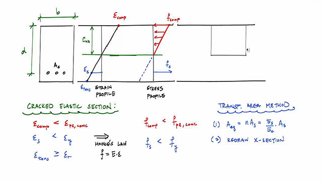
In one way slab, the main reinforcement is calculated with a formula (In limit state design) and to obtain the result the comparison is made between the comparing compressive force and tensile forces.

Ast = 0.5 Fck/Fu[1-√1-2.6Mu/Fck.b.d]b.d
and the distribution steel is calculated as

0.15% of Ag, for mild steel.
0.12% of Ag, for tor steel.
Where, Ast denotes Area of the steel in tension.
Fu denotes Ultimate strength of steel.

Mu denotes Ultimate moment of resistance.
b denotes Breadth of the slab section.
d denotes Depth of the slab section.
Ag denotes Gross area of the section.

DETAILS OF ONE WAY SLAB REINFORCEMENT

Article Source : www.dailycivil.com

~~~~~~~~~~~~~~~~~~~~~~
Published By
Rajib Dey
~~~~~~~~~~~~~~~~~~~~~

Wednesday, February 15, 2017

DEFINITION OF UNDER REINFORCED AND OVER REINFORCED SECTION

BALANCED SECTION:
Balanced section refers to the section in which the quantity of steel is just adequately arranged so that the concrete in compression zone and steel in tension zone attains its acceptable stresses instantaneously.

In this section, the critical depth is identical to its actual depth. i.e n = Na = Nc

UNDER REINFORCED SECTION:
In this section, the quantity of steel is insufficient to produce the highest concrete fibers in the compression area to be compressed with their highest allowable stress.

In this section, the quantity of steel is insufficient to arrange the concrete for being compressed in compression area to their maximum allowable value. It signifies the steel is arranged below that a balanced section needs. In under reinforced section, the depth of actual Na is under the critical Na.

i.e; Na < Nc

OVER REINFORCED SECTION:
In this section, in tension zone, the quantity of steel remains in excess of the quantity of steel necessary to arrange compressive zone concrete to be compressed to their highest permissible value. Alternatively, if the highest compressive stress in concrete attains its permissible limit, the comparing tensile stress in steel will not surpass its allowable value.

So in over reinforced section, the depth of actual Na is over and above the critical Na.

i.e; Na > Nc
DEFINITION OF UNDER REINFORCED AND OVER REINFORCED SECTION

~~~~~~~~~~~~~~~~~~~~~
Published By
Rajib Dey
~~~~~~~~~~~~~~~~~~~~~

Tuesday, February 14, 2017

How to obtain the quantity of 1.226 cft in 1 bag cement

This construction video is recorded on the detailed process for obtaining the quantity of 1.226 cft cement in 1 bag.

Here density of cement is taken as 1400 kg per m3 (m = millimeter)

Therefore, the quantity of cement for 1m3 = 1440 Kg

It is assumed 1 bag cement = 50 kg
Therefore, cement required for 1m3 = 1440/50 = 28.8 bags (This is taken as equation 1)
It is assumed 1m3 = 35.3147 CFT (Cubic Feet) (It is taken as equation 2)

By combining both equation, the following result is obtained :-

28.8 bags similar to 35.3147 CFT

Therefore, 1 bag is similar to 35.3147/28.8 = 1.226 CFT


~~~~~~~~~~~~~~~~~~~~~
Published By
Rajib Dey
~~~~~~~~~~~~~~~~~~~~~

Friday, February 10, 2017

Process for creating design of Seismic Tie Beams

Tie beams are constructed to support the differential settlement among the isolated footings other than the vertical loads of the block works.

With reference to ACI 318-08 section 21.12.3.2, grade beams which are built up to function as horizontal ties among pile caps or footings should be proportioned in such a way so that the smallest cross-sectional dimension is identical to or exceeding the clear spacing among associated columns divided by 20 but should not be over 18 inches. Closed ties should be arranged at a gapping not surpassing the lesser of one half the lowest orthogonal cross-sectional dimension and 12 inches.”

But, it becomes difficult to understand that what force these tie beams are required. In this regard, IBC 2009 section plays an important role.

IBC2009 section 1809.13 for shallow foundations and 1810.3.13 for deep foundations.

For SDC C, D, E or F, ties have the capacity to bear, in tension or compression, a force similar to the smaller of the product of the larger pile cap or column design gravity load times the seismic coefficient, Sds, divided by 10, and 25 percent of the smaller pile or column design gravity load.

In brief, Tie beam force; FT = Larger of ( Pu_large x Sds /10 , Pu_small x 25%)

Process for creating design of Seismic Tie Beams

~~~~~~~~~~~~~~~~~~~~
Published By
Rajib Dey
~~~~~~~~~~~~~~~~~~~~

Wednesday, February 8, 2017

Variation among Working stress method and Limit state method

This construction video shows the variation among working stress method and limit state method.

The basic variance among Working state method (WSM) and Limit State method (LSM) is that WSM stands for an elastic design method while LSM stands for a plastic design method.

In elastic design method, the design strength is estimated in such a manner that the stress in material is controlled with its yield limit, under which the material adheres to Hooke's law, and therefore, the word "elastic" is utilized. This method is used to produce cost-effective design of simple beam, or other structural elements where the standard for evaluating the design is stress (static). But, in case of changing the evaluation standard to other factors like fatigue stress, both the methods will give similar design. Also, WSM substantially reduces the calculation efforts.

In plastic design method the stress in material is permitted to go outside the yield limit and move into the plastic zone to attain extreme strength. Therefore, the "moment-rotation" power of beam, as for instance, is applied for creating more cost-effective design. However, because of the deployment of the non-linear zone, this method comprises laborious calculation.

Given below, some other general differences:

1) Serviceability check if LSM is necessary since after the elastic region strain is greater, it leads to more deformation, therefore a check is required.
2) LSM refers to strain based method while WSM is stress based method.
3) LSM refers to non-deterministic method while WSM is deterministic approach.
4) Partial safety factor is applied in LSM while Safety factor is applied in WSM.
5) Characteristic values (resulting from probabilistic approach) are applied in case of LSM while Average or statistic values are applied in WSM.


~~~~~~~~~~~~~~~~~~~~~
Published By
Rajib Dey
~~~~~~~~~~~~~~~~~~~~~

Monday, February 6, 2017

How to measure steel for pier, pile and circular column with circular ties

This construction video offers detailed guidelines for measuring the steel quantity in circular column, piers, and piles.

Some vital information on circular column, pier and pile :-

Circular columns are uniform about any centroidal axis. The circular column contains a smaller cross section area (0.785 times the square column) but greater second moment of area (1.178 times the square column). There is less susceptibility for Circular column to buckling and it needs little more reinforcement to bear the identical load like a square column. Besides, circular sections contain unvarying torsion characteristics. Least number of bars necessary in a circular column is 6. There does not exist any weak corners as well as stress concentration in circular columns.

A pier refers to an elevated structure usually supported with well-spaced foundation system. The foundation system ranges from a Pile, Caisson or simple brick pillar that is formed on the basis of the sub-soil condition. The Pile and Caisson are set of deep foundations.


~~~~~~~~~~~~~~~~~~~~
Published By
Rajib Dey
~~~~~~~~~~~~~~~~~~~~

Saturday, February 4, 2017

How to place stirrups with proper structural drawings in a column

This construction video is recorded on the topic of how to organize stirrups for a column that contains 12nos of vertical bar. Learn to apply various structural drawings for organizing stirrups.

Stirrup can be defined as follows :-

1. A reinforcement useful for withstanding shear and diagonal tension stresses in a concrete structural member.

2. A steel bar that is curved into a "U" or box shape and arranged perpendicular to, or at an angle to the longitudinal reinforcement, and perfectly anchored.

3. Lateral reinforcement that is developed with separate units, open or closed, or of uninterruptedly wound reinforcement. The word stirrups is generally used with lateral reinforcement in flexural members and the term is linked with lateral reinforcement in vertical compression members.

Concrete beams contain different depth. If the beam contains more depth, the shear strength will be increased. If the depth is insufficient, steel stirrups should be included to enhance the shear strength of the beam. These stirrups generally refer to one piece of steel that is curved into a quadrilateral shape. Generally small diameter steel like #3 and #4 rebar is applied. The stirrup normally covers around the bottom and top bars of the beams.

As the stirrup is built up from two pieces having insufficient lap splice, it is recommended to set up a stirrup simultaneously when the horizontal reinforcement is being set up.


~~~~~~~~~~~~~~~~~~~~~
Published By
Rajib Dey
~~~~~~~~~~~~~~~~~~~~~

Friday, February 3, 2017

How the functionality of concrete is affected by the different factors

Quantity of water
Size aggregates
Grading of aggregate
Shape of aggregate
Texture of aggregate
Ratio of concrete

QUANTITY OF WATER.
Water is considered as the most vital factor that can influence the functionality of concrete. If more water is added, the functionality of the concrete will be enhanced. But with the inclusion of too much water, the durability of concrete can be reduced.

SIZE OF AGGREGATES
If the size of the aggregate is increased, the functionality of the high strength concrete will be reduced whereas the functionality of normal strength concrete is raised with the increment in the size of the aggregates.

GRADING OF AGGREGATES
If the grading of the aggregates is superior, the strength of the concrete along with the functionality is enhanced. The functionality of the concrete becomes superior with least number of voids. As for example, if there are 5%viods, the strength of the concrete will be reduced by 30 percent.

SHAPE OF AGGREGATE
The functionality of concrete is influenced by the shape of aggregate. The cubic shaped aggregate is mostly recommended. The functionality of the concrete is greatly affected by the stretched and odd shaped aggregate. The longevity of such concrete is also decreased. The functionality of the concrete is increased if the concrete contains rounded aggregates. But in this situation, the bond of the concrete remains extremely weak.

TEXTURE OF CONCRETE
Texture of aggregate is another crucial factor to influence the functionality of concrete. In order to develop a concrete, porous aggregate needs more water and thus the functionality of concrete is reduced.

RATIO OF CONCRETE
The functionality of concrete is also influenced by the ratio of fine aggregates and the course aggregate. If the number of fine aggregates in concrete is increased, the functionality of the concrete becomes superior. As for example, if the quantity of the cement is increased, the functionality of the concrete enhances.

To read the complete article, go through the following link


How the functionality of concrete is affected by the different factors

~~~~~~~~~~~~~~~~~~~~
Published By
Rajib Dey
~~~~~~~~~~~~~~~~~~~~

Thursday, February 2, 2017

How to design R.C.C lintels

Now-a-days, the R.C.C lintels are mostly recognized to extent the openings for doors, windows, etc. in a structure owing to their firmness, inflexibility, fire resistance power, cost-effectiveness and simplicity in construction. R.C.C lintels are recommended for all the loads and for any span. The width of lintel is similar to width of wall. Depth of lintel is based on the length of span and magnitude of loading.

Lintel can be made from various materials. Such as steel, wood, stone, RCC, etc.

Generally, the most effective material for lintel is RCC (Reinforced Cement Concrete). Generally, applied concrete ratio for RCC lintel is 1:2:4.

On the basis of the casting methods, RCC lintel is classified as Pre-cast RCC lintel and Cast-in-place RCC lintel.

DESIGN METHOD OF R.C.C LINTEL

There are similarities between the design methods of a lintel (single span or continuous having a few openings) and the design methods of a simple beam.

1. The lintel width is same as the wall thickness.

2. Provide an appropriate depth of the lintel.

3. Select the operational span of the lintel (maintain rational end bearings and real depth).

4. Assume W as the aggregate weight of the masonry work wrapped in the triangle, supposing that conditions authorize triangular load of the workmanship on the lintel.

5. Estimate the extreme bending moment (M1) at the centre of the lintel ( because of the triangular load).
M1 = Wl/6

Now estimate the maximum bending moment (M2) because of the self-weight (w) of the lintel per metre length.
M2 = wl^2/8

To read the complete article, go through the following link www.dailycivil.com

How to design R.C.C lintels

~~~~~~~~~~~~~~~~~~~~~
Published By
Rajib Dey
~~~~~~~~~~~~~~~~~~~~~