adsense analytic

Friday, October 28, 2016

Tips to calculate a stair

This construction video briefly describes how to estimates the stairs by following some easy to follow processes. By watching this construction video, you can learn the basics of making measurements. If you can learn how to estimate each part properly, you will be able to make an efficient stair construction and design. Estimation includes measurements, number of steps, steps sizes, slop ratio, angle of slope as well as length, height, depth of a stair.


~~~~~~~~~~~~~~~~~~~~~
Published By
Rajib Dey
~~~~~~~~~~~~~~~~~~~~~

Thursday, October 27, 2016

Virtual Work Method For Frames

Forces operating on frame can cause three types of internal forces like bending moment, axial force and shear force. Therefore, it is possible to view frame member as combination of truss and beam member.

In a simple term, virtual work method can be defined as “Completed External work is identical to completed internal work”.

In frames, axial deformation is generally small corresponding to bending deformation and it is normal to disregard axial deformations. In this video, all the prospective deformations are considered.

Virtual Work facilitates to work out determinate and indeterminate structures as well as estimate their deflections. Therefore, it can obtain everything that all the other methods can attain collectively.

Using the virtual work equations to a frame structure is very easy like segregating the frame into a series of “beams” and measuring the virtual work for each section.

Besides, while assessing the deformation of a frame structure, it is essential to take into consideration both bending and axial internal force components.


~~~~~~~~~~~~~~~~~~~~~
Published By
Rajib Dey
~~~~~~~~~~~~~~~~~~~~~

Wednesday, October 26, 2016

Download excel sheet for designing a pile cap

A pile cap stands for a compact concrete material that is supported with concrete or timber piles driven into soft or unsettled ground to build up a perfect durable foundation. It generally develops part of the foundation of a building, specifically a multi-story building, structure or support base for heavy equipment. The load of the building is transmitted by the cast concrete pile cap into the piles. Raft is the same structure to a pile cap and it is a concrete foundation floor supported with soft soil that is accountable for subsidence.

DESIGN METHOD

Settle number of pile
Placement of pile cap and plane dimension
Pile cap elementary depth
Verify forces in piles
Verify punching shear
Verify shear
Design of moment
Verify bond
Details for reinforcement

How to measure Reinforcement  with column & footing

~~~~~~~~~~~~~~~~~~~~~~
Published By
Rajib Dey
~~~~~~~~~~~~~~~~~~~~~~

Tuesday, October 25, 2016

How to measure Reinforcement with column & footing

This construction video provides step-by-step guidelines on estimation of Reinforcement with column and footing as per construction drawing. The video will be very useful for foundation design.

Reinforcement is essential for reinforced concrete members like footings, beams, columns, slabs, lintels etc. It is recommended to estimate reinforcement quantity before tendering phase for measuring cost of project or construction work roughly.

If working drawings and schedules for the reinforcement are unavailable, then it is required to create an estimate of the projected quantities. The quantities are usually defined according to the requirements of the Standard method of measurement of building works.


~~~~~~~~~~~~~~~~~~~~~
Published By
Rajib Dey
~~~~~~~~~~~~~~~~~~~~~

Monday, October 24, 2016

Use of Excel Spread Sheet by a Quantity Surveyor for Material Stock Taking

This video will provide you use of Excel Spread Sheet by a Quantity Surveyor for Material Stock Taking On-Site.wmv.

We provides accurate material takeoffs for some or all phases of Construction including elevation plan, concrete foundation, site concrete and cast-in-place concrete both for private and public biddings. We generate accurate quantity take-off from plan sheets on any structure in spite of size.


~~~~~~~~~~~~~~~~~~~~~
Published By
Rajib Dey
~~~~~~~~~~~~~~~~~~~~~

Thursday, October 20, 2016

How to design and detail the RCC Beams

RCC beams structural elements are formed to bear transverse external loads that produce bending moment, shear forces and in some cases torsion over their length. Concrete performs well in compression but feeble in tension. The role of Steel reinforcement is to combat tensile stresses in reinforced concrete beams.

Now-a-days deformed and twisted bars are extensively used in RCC work. Deformed or High yield strength deformed bars (HYSD) contains ribs on the surface. It improves the stability of bond by minimum 40% with regards to that of mild steel bar.

Fine detailing of reinforcements with exact drawings is necessary at the job site to optimize the construction procedure. Usually, there is a bar bending schedule contained with these drawing. The bar bending schedule defines the length and number, position and the shape of the bar.

The detailing of beams generally involves the followings :

i) Size and number (or spacing) of bars,
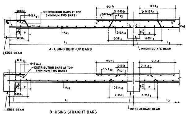
ii) Lap and curtailment (or bending) of bars,
iii) Development length of bars,
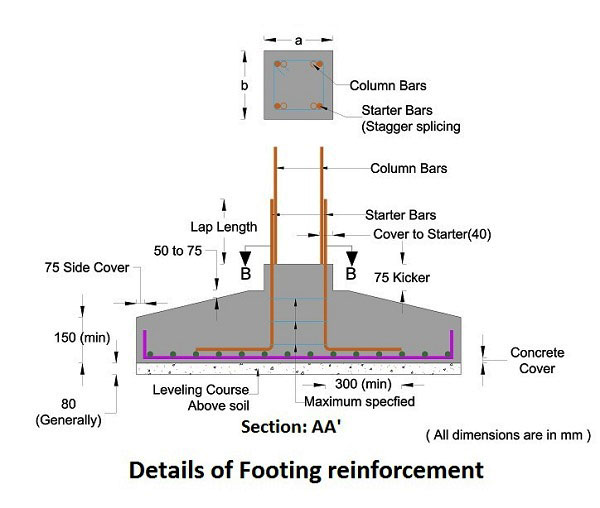
iv) Clear cover to the reinforcement and
v) Spacer and chair bars

Anchorage in steel bars is demonstrated with bends and hooks. Hooks do not include Twisted steel bars or deformed steel bars. The anchorage value of bend of bar is captured as 4 times the diameter of bar for each 450 bend that depends on maximum of 16 times the diameter of bar. To expand the length of bars, bars are lapped over one another. Lowest lap length is identical to development length. Development length for bars in various concrete mix is provided in tables 4.2 to 4.4 of SP34.

The value of K given above is subjected to type of steel applied that is provided below :-

The beams are categorized as:

  • Based on shape: Rectangular, T, L, Circular etc.
  • Based on supporting conditions: Simply supported, fixed, continuous and cantilever beams
  • Based on reinforcement: Singly reinforced and doubly reinforced

Depth of the beam is obtained on the basis of flexural strength and satisfying the deflection criteria. Usually the ratio of span to depth ratio is retained as 10 to 15 and the depth to width ratio of rectangular is maintained in the range of 1.5 to 2.

Lowest cover in beams should be 25 mm or not below the larger diameter of bar for all steel reinforcement together with links. Minimal cover provided in Table 16 and 16A of IS456-2000 should be applied to meet the stability criteria.

To read the complete article, go through the following link theconstructor.org

How to design and detail the RCC Beams

~~~~~~~~~~~~~~~~~~~~~
Published By
Rajib Dey
~~~~~~~~~~~~~~~~~~~~~

Wednesday, October 19, 2016

Concrete Footings – Some useful guidelines

Usually, it should be examined when the footings are arranged for concreting i.e. reinforcement is completely engrossed but it is recommended to examine it in two phase i.e.

01. Initially verify formwork prior to arrange reinforcement. This is very useful because finding out & rectifying formwork defect is very difficult once the reinforcement is organized in position.

02. Checking reinforcement – Therefore, it is suggested to initially verify the formwork prior to place or tie reinforcement.

01. Centering and shuttering / Formwork:

While starting the shuttering & centering / formwork for footing , abide by the following points.

  • Verify the center lines / margin from boundary etc. from reference column/bench mark pillar, boundary distance from roads and obviously orientation regarding North.
  • Make sure that the foundation is laid at a designed depth according to drawing.
  • Size of formwork box should be according to drawing and it should be formed with correct materials.
  • The formwork should have been dry and be refined cautiously prior to use mould release agent. The similar type of release agent should have been applied through on identical formwork materials.
  • The surface of formwork should have been uniform and delicately coated with mould release agent.
  • The mould release agent should not be contacted with reinforcement or the solidified concrete.
  • The height of shuttering must be similar with the height of pedestal and joint should have been closed to avoid any leakage of cement pulp.
  • Footing box should have been supported correctly in order that the placing of footing box should be unchanged throughout concreting.
  • Centre of the footing is stamped with the nail on planks or footing box.
  • Foundations shuttering should be strong in dry or even rainy situations or even when ground water exist.
  • Prior to tying reinforcement, get the shuttering sanctioned by Engineer-in-charge or supervisor.
  • Ensure that there is no earth collection on C.C. prior to tying reinforcement.
  • If foundation depth increases, make sure that the excavated earth does not slide or drop unless it is refilled. Accomplish perfect shoring and shuttering. Make sure that suitable ladder etc to enter the pit and for coming out. Besides, examine the safety of labor’s working.
To read the complete article, go through the following link gharpedia.com

Concrete Footings – Some useful guidelines

~~~~~~~~~~~~~~~~~~~~~
Published By
Rajib Dey
~~~~~~~~~~~~~~~~~~~~~

Tuesday, October 18, 2016

Construction Materials & Quality Control in construction site for Civil Engineering

Countless types of Building materials are used in the construction industry to create buildings and structures. These groupings of materials and products are used by architects and construction project managers to state the materials and techniques used for building projects.

BTech Engineering has presented an useful information which will assist engineers in construction worksite for determining the quality of construction materials. Construction Materials and Quality Control that used in construction of buildings like First class bricks quality, properties of sand, cements quality much more materials aggregates, stones, steel and so on.

Study the following video attentively:

~~~~~~~~~~~~~~~~~~~~~
Published By
Rajib Dey
~~~~~~~~~~~~~~~~~~~~~

Friday, October 14, 2016

Edificius – The most powerful software for architecture, engineering & construction sectors

ACCA Software SpA has developed Edificius, the leading professional software specially designed for architecture, engineering and construction. With Edificius, one can simplify the 3d architectural design process.

This Architectural BIM Design software can easily produce various construction documents like floor plans, elevation views, cross-sections, isometric and perspective views with a simple 2D or 3D input.

Every step of the BIM modelling phase is similar to an automatic and dynamic deviation of the pertaining construction documents adopting from the project. This will save huge time and get rid of errors.

With the 3D Edificius Architectural Design software, it is possible to instantly and smoothly explain the building’s BIM model with parametric architectural BIM objects exactly for 3D architectural design.

Edificius allows the users to instantly and simply generate the building’s BIM model that functions with both plan view (2D) or directly in the 3D modeling atmosphere through parametric architectural objects.

With “building envelope” objects, “curved building envelope” and “horizontal building envelope” it becomes easier to draw different types of load bearing walls, curtain walls, floors, walls and internal partitions. Isolate inner spaces from the outside, demarcating rooms and compartments and automatically obtain volumes and surface data, both for urban planning parameter assessments and for organizing the initial stages of what will then turn out to be the project’s cost estimate.

With the “curtain wall” and “curved curtain wall” objects, outline curtain wall facades (together with windows), etc.

There are user-friendly functional tools within roof object to model all types of pitched roof slabs.

To get more information, go through the following link 

Edificius – The most powerful software for architecture, engineering & construction sectors

~~~~~~~~~~~~~~~~~~~~~
Published By
Rajib Dey
~~~~~~~~~~~~~~~~~~~~~

Thursday, October 13, 2016

How to use excel for carrying out complex engineering calculations for structural analysis

This construction video is extracted from a construction course conducted by GrSoft Structural Engineering. This course will provide guidance on how to use Microsoft Excel to resolve complicated engineering calculations. In excel, there is powerful programming capabilities to solve all the engineering calculations easily.

Excel contains various input parameters which can be entered on a very easy and a rapid way. Besides, there is also a simple sketch that can be used as a graphical illustration of the basis of calculation having annotations of input parameters. The engineers can also apply the simple mathematical process as well as write various complicated formulas or iterations. Generate your own customized engineering calculations quickly. Update formulas in your calculation when necessary. Excel provides open-source solution with robust programmable tools.

Learning Objective:

- How to generate cells where input parameters are inputted
- How to produce a sketch with annotations of input parameters
- How to arrange cells where results of calculation will be written
- How to generate a push button to initiate start of the calculation
- How to write code to execute calculation
- How to write code to show the outcomes of the calculation
- How to carry out calculation
- How to customize excel for creating practical engineering calculation for structural analysis


~~~~~~~~~~~~~~~~~~~~~
Published By
Rajib Dey
~~~~~~~~~~~~~~~~~~~~~

Thursday, October 6, 2016

A useful video tutorial on drawing Shear Force and Bending Moment Diagram

This construction article briefly demonstrates how to draw SFD and BMD. SFD stands for Shear Force Diagram and BMD stands for Bending Moment Diagram. These two play a major role for creating the design of members.

Specific parameters are necessary for each design method to design the capacity of members. These parameters act as input in design process and as an end result there will be cross-sectional and material properties.

This video focuses on graphical approach to demonstrate how analysis of a simply supported beam is prepared and drawing is made for shear force and Bending moment diagram. Conventions are similar to that applied in software like etabs and sap2000. Bending Moment is positive downward with the purpose of clarifying in superior manner where reinforcement should be positioned.


~~~~~~~~~~~~~~~~~~~~~
Published By
Rajib Dey
~~~~~~~~~~~~~~~~~~~~~

Wednesday, October 5, 2016

How to use fast setting plaster to skim coat over cinder block walls

This construction video will introduce step-by-step processes for making your plastering work efficient with any rapid set plaster. The video provides information on how to skim coat or render plaster over cinder block walls with the use of rapid set plaster.

Here the Portland cement is used for plastering work. Rapid set plaster is applied to achieve quicker set times, greater stability, higher strength, marginal shrinkage and reduced cracking.


~~~~~~~~~~~~~~~~~~~~~
Published By
Rajib Dey
~~~~~~~~~~~~~~~~~~~~~

Tuesday, October 4, 2016

Details of Machine Foundation

The design of machine foundation is carried out for evaluating vibration characteristics of the foundation system cautiously. The machine manufacturer supplies the appropriate data essential for the design and development of the machine foundation of machine before creating the design. All parts of machine foundation are created for extreme stresses because of the poorest combination of vertical loads, torque, longitudinal and transverse forces, stresses because of dissimilarity in temperature and the foundation dead load. In case, the machine foundation layout is partially constructed with beam and column construction, straight bars are placed both at top and bottom of the beams and the gaping of the stirrups should be nearby. The primary foundation block must contain the calculated thickness and should be reinforced both at top and bottom, although the reinforcements are not compulsory from design considerations.

General standards of machine foundation design are provided below :-

There should be adequate mass of the foundation block to absorb vibrations and as well as withstand resonance among the machine and the adjoining soil. This is possible with the increased weight of foundation block according to the power of the engines. It is recommended that for every break horse power of multicylinder engines, a lowest 725 kg. weight of foundation should be arranged for gas engines, 565 kg. for diesel engines and 225 kg. for steam engines. This value is raised by 40 to 60% for the single cylinder engines. As a thumb rule, the weight of the foundation must be minimum 2½ times the weight of the entire machine.

To get rid of the variation in settlement, the dimension of the machinefoundation should be perfect so that the subsequent force move through the centre of gravity of the base contact area as a result of the weight of the machine and the weight of the foundation.

The foundation should have been solid enough to maintain required strength as the smallest deflection of foundation can lead to significant bearing troubles.

There should be a gap around the machine foundation so that the vibration is not delivered from the machine to the adjacent parts of the building to separate it from the adjoining parts of the building.

Overhanging cantilevers should not be used in most cases. If it is not possible, they should have been designed for stability and hardness against vibrations.(6) All units of machine foundation are arranged with reinforcement passing both ways along the surface of the concrete block. The concrete cover to the reinforcement must not be below than 75 mm at the bottom, 50 mm on sides and 40 mm at the top. For foundation developed with steam turbo-generators, cover for the reinforcement at bottom, side and top of base slab must not be below 100 mm.

The amount of reinforcement in foundation units should not be below 2 kg per cu. m of concrete toward impact type or reciprocating type of machines, 50 kg per cu. m of concrete for rotary type of machines and 100 kg per cu. m of concrete for steam turbo generators.

M 150 to M 200 grade of concrete should be applied in the foundations and mostly the-entire block should be concreted in one process devoid of construction joints.


ADAPT-Builder Suite – A useful construction software

~~~~~~~~~~~~~~~~~~~~
Published By
Rajib Dey
~~~~~~~~~~~~~~~~~~~~

Saturday, October 1, 2016

ADAPT-Builder Suite – A useful construction software for designing conventionally reinforced concrete structures

ADAPT Corporation has developed ADAPT-Builder Suite that is used to make complete analysis of concrete buildings. This construction program is useful for General Structural Analysis, Analysis of Plates, Analysis of Frames, Analysis of Beams, Concrete Design, Analysis of Columns, Wind Loading, Foundations.

It contains Edge, Floor Pro and MAT etc. Edge makes analysis of complete building model for lateral and gravity load. Floor Pro is applied to make the comprehensive design of any concrete floor system with or without post-tensioning. MAT is used for producing the innovative design of foundations. There is also an optional column design module that provides support with a well-organized workflow for creating the cohesive design of vertical elements in a structure.

A robust and easily adoptable 3D finite element engine makes the Builder an exceptional construction software to perform the modeling and analysis of any concrete building efficiently.

Builder’s modules are compatible with an extensive range of international codes. Besides, they are well suited with simplified BIM workflows and can be easily incorporated with Revit Structure and other structural analysis packages.

To get more information, visit 

ADAPT-Builder Suite – A useful construction software

~~~~~~~~~~~~~~~~~~~~~
Published By
Rajib Dey
~~~~~~~~~~~~~~~~~~~~~