adsense analytic

Tuesday, May 31, 2016

Trimble introduces new software series of Tekla to streamline BIM analysis & design process

Trimble recently launched three new versions of its building information modeling (BIM) and analysis & design software like Tekla Structures 2016Tekla Structural Designer 2016 and Tekla Tedds 2016 for engineering and construction professionals. These newly launched software offer superior collaboration and improved workflow toward structural steel and precast concrete designers, detailers and fabricators, concrete contractors, general contractors and structural engineers.

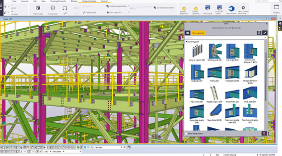
Tekla Structures 2016: Tekla Structures is the most sophisticated BIM software that can be used for generating perfect, constructible modeling concerning any steel or concrete structure. This most updated version makes the modeling process smarter as well as enhances productivity by simply preventing precious errors in the fabrication and construction stages. The software supports 17 languages together with Korean language.

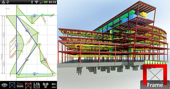
Tekla Structural Designer 2016: Tekla Structural Designer 2016 facilitates the engineers to evaluate and design buildings competently. With this latest version, the performance is significantly improved in both modeling and processing time at the time of examining and designing structures. Now it becomes easier to deal with even bigger and more demanding models efficiently.

The seismic design capabilities of the software are now supported with added structural design and detailing checks for concrete structures adhering to U.S. codes. It is suitable to be utilized for higher classified earthquake regions.

Tekla Tedds 2016: The new version of Tekla Tedds, provides a solution for computerizing recurring structural calculations. New options convey more resilience and alternatives in favor of the analysis and design of retaining walls, foundations and steel and concrete beams adhering to both the U.S. building codes and Eurocodes.

Availability: In order to download the newest series of Tekla Software, visit -

To get more updates on Tekla software, visit www.tekla.com. Tekla Corporation changed to the Trimble brand in January 2016. More information about rebranding is available at www.tekla.com/evolution.

BIM Analysis Software
Image Courtesy: tekla.com
~~~~~~~~~~~~~~~~~~~~~~
Published By
Rajib Dey
~~~~~~~~~~~~~~~~~~~~~~

Vacancy For Structural Engineer In Birmingham

Are you a Structural Engineer? Experience within Structural Engineering but ready to expand on your knowledge and skill set? Then this is the perfect job role for you. Our client is based within the Birmingham area so will be easily accessible from surrounding areas and also is a prestigious company who is excelling in various markets and create impressive CAD software.

Job Opportunity:

Candidate will have the opportunity to work with their popular software and be part of an innovative and professional team. This Structural Engineer will have the opportunity to put your practical design skills to use and be involved in the fantastic software that the company creates.

Skills required for this job:

A degree in Structural Engineering or equivalent
Must have experience of AutoCAD or CAD/CAE
An innovative mind and hands-on problem solving abilities
Good understanding of 2D and 3D
Ability to work from first principles with strong mathematical analysis.
So without any delay proceed further to appear in the interview. Interviews are being arranged very soon. Don't forget to browse the Ascent People website to find out more opportunities that will come handy for you.

Candidates from all ages and backgrounds will be considered for this role. Ascent People Ltd are acting as an employment agency for this role.

Location: Birmingham, West Midlands (County)
Salary Structure: £30000 per annum + Package
Company: Ascent People Ltd
Job Type: Permanent
Facilities: 25 days' holiday, pay reviews, flexible working hours, free parking and pension scheme
Contact: Megan Barrow
Reference: CWJobs/mseb
Job ID: 65669871
Vacancy for Structural Engineer in Birmingham

~~~~~~~~~~~~~~~~~~~~~
Published By
Rajib Dey
~~~~~~~~~~~~~~~~~~~~~

Monday, May 30, 2016

How To Build Up A Baby Basement

This construction video focuses on developing Baby Basement. The Glatthaar Baby Basement is very cost effective and it offers extra space under the ground bearing slab. The basement is utilized as a storing or utility room as well as wine cellar etc. It is situated wherever determined in the architectural drawing. Baby basement is found in concrete staircase, lightwells, external entrance, etc.

The process includes the following :-
Shuttering of foundation slab
Positioning of membrane & spacers
Positioning of reinforcement
Completed foundation
Pouring of foundation slab
Levelling & trowelling
Completed foundation slab
Set up twin wall panels
Set up floor panels
Filling twin wall cavity
Completed basement installation
Arrangement of ground floor slab
Footings and shuttering of ground floor slab
Positioning foul drainage pipes
Pouring frost protection
Positioning membrane & spacers
Positioning reinforcement
Pouring ground floor and basement slab
Finished baby basement through ground floor slab


Specifications of the Glatthaar Baby Basement:

Foundation slab
The dimensions of the foundation slab range from 4,80 m or 9,60 m (length) x 4,80 m (width). A polythene Membrane is set up below the ground bearing slab. The concrete surface is left lightly tamped or completed through hand trowels. Thickness of the foundation slab, nominal 250 mm insitu concrete C25/30 (as supposed perfect).

External basement walls
The external walls are developed with storey height, pre-cast concrete composite panels include an inner and outer leaf perpetually joined with reinforcement. Panels are set up butt-jointed on the foundation slab that is built up earlier. Each panel thickness nominal 240 mm is mass-produced from a C25/30 concrete, fair faced is completed on the face of both leaves with joints left uncovered. The internal structural height belongs to 2,40 m. Opening for service pipes and sealing flanges (max. 3 piece) are contained.

Ground floor / Basement slab
The floor slab, thickness nominal 180-200 mm, contains both pre-cast and insitu concrete C20/25. Supplimentary reinforcement is settled on site. The cavity amid the leaves of the basement wall is stuffed with insitu concrete and poured with the ground floor basement slab for developing a monolithic, box-like structure.

Waterproofing and insulation
Glatthaar is completely water-resistant to the structure. The waterproof structure is attained by using BS 8102 Type A (Tanking) or Type B (structural integral protection) as supposed perfect. The foundation slab and the wall panels contain waterproof concrete. Max. 4 sealing flanges are contained. The complete external walls are covered with a 40 mm insulation board and a backfill protection.

~~~~~~~~~~~~~~~~~~~~~
Published By
Rajib Dey
~~~~~~~~~~~~~~~~~~~~~

Friday, May 27, 2016

Elevator Shaft Reinforced Concrete Shear Wall Details

Elevator (lift) Shaft Reinforced Concrete Shear Walls detail is a CAD dwg drawing that contains “Π” shaped elevator shaft shear wall with primary and secondary column reinforcement.

There are various details in this drawing which range from main and secondary column reinforcement rebars, stirrups, links details, shear reinforcement. This template is very essential to save huge time in your projects. Dimensions of this elevator-lift shaft shear wall can be modified efficiently through some easy to follow CAD commands, spreading the middle light reinforced part of each shear wall devoid of modifying the main column reinforcements.

Other Elevator Shear Wall Details include the following :

– Elevator Shaft Pit Foundation Reinforcement Detail
Reinforced Concrete Column Supported on Mat ( spread ) Foundation
– Shear Wall Reinforced Concrete Column Reinforcement Details


~~~~~~~~~~~~~~~~~~~~~
Published By
Rajib Dey
~~~~~~~~~~~~~~~~~~~~~

Thursday, May 26, 2016

An Exclusive Animated Construction Video On Spider Tie Concrete Wall Forming System

This animated construction video specifically narrates Spider Tie Concrete House. Spider Tie is a recognized concrete wall forming system. It reduces heavy form as well as labor cost & time for construction. The Spider Tie system generates a temporary frame work through which you just affix your plywood with the use of a approved coarse thread screw. It has similar functionality with binding plaster to wooden studs. This framework can retain your re-bar correctly in place each time devoid of applying tie wire.


~~~~~~~~~~~~~~~~~~~~~
Published By
Rajib Dey
~~~~~~~~~~~~~~~~~~~~~

Wednesday, May 25, 2016

Brief Overview Of Concrete Construction Process

David Moloney comes up with this exclusive construction film that contains video footage, photographs, 3d animation and images to easily demonstrate the detailed concrete construction progression as well as related construction equipment. This construction video covers the topics like Batching, Placing, Compaction,Testing, Formwork, Falsework, Tunnel, Piling, Diaphragm Walls,Post-tensioning and Reinforcement cutting & bending, Precast, Quarry and Aggregate Production. Cement Manufacture, Slip-form pavements and towers.


~~~~~~~~~~~~~~~~~~~~~
Published By
Rajib Dey
~~~~~~~~~~~~~~~~~~~~~

Monday, May 23, 2016

Designers Ron Culver & Joseph Sarafian Jointly Develop An Exclusive Method To Cast Concrete In Lycra Stretched With Robotic Arms

Both the designers Ron Culver and Joseph Sarafian have discovered a unique system for casting concrete in Lycra stretched with robotic arms. This newest method can be applied to develop basic new architectural forms (+ movie).

The Fabric Forms project comprises pouring a concrete fibreglass mixture into Y-shaped Lycra sleeves stretched into position through six-axis robots.

This casting system can be implemented at different scales in the construction jobsite in near future. It can be expanded to form unique building facade elements as well as the primary structure of a building.

With its simple production capacity, the fabric facilitates the users to generate various shapes devoid of casting a unique mould each time they create a new shape.

Fabric Forms facilitate to produce compound curvature beyond a cast object that would otherwise be lost once rigid formwork is eliminated.

It is considered as a more endurable substitute that can minimize labor and material costs. It is more rapid process as compared to conventional construction methods.

Conventional casting methods are both laborious and unsupportable as plywood formwork is frequently exposed and casted off as soon as concrete has cured.
When the concrete is set, the fabric is then exposed that leads to marginal waste. The pieces will require roughly 45 minutes to solidify and are set collectively through a 3D-printed coupler for generating larger assemblies that could be later on utilized as attractive facades or even load-bearing structures.


~~~~~~~~~~~~~~~~~~~~~
Published By
Rajib Dey
~~~~~~~~~~~~~~~~~~~~~

Saturday, May 21, 2016

REBARS Is A Spreadsheet Program To Determine Reinforcing Bar Development And Splice Lengths For Steel Reinforcement

"REBARS" is a MS-Excel based spreadsheet program useful for ascertaining reinforcing bar development and splice lengths specially, the development lengths and splice lengths for straight bars in tension as well as compression. Besides, the development length for standard hook bars is calculated. The provisions for development and splice lengths are contained in high seismic risk applications by adhering ACI 318-05. There also exists a worksheet that consists of reinforcing bar data tables. This version is developed on the basis of the ACI 318-05 Code.

Program Assumptions and Limitations:

1. This program abides by the methods and guidelines of the ACI 318-05 Building Code, Chapters 12 and 21.

2. The "Calc Development" worksheet, for a specified reinforcing bar size, establishes the straight development and splice lengths toward a "top" bar and an "other" bar in tension, the straight development and splice lengths for the bar in compression, and the tension development length of the bar as a standard hook, all at once. A comprehensive table of reinforcing bar development and splice lengths is also generated for #3 over #18 bars. 

3. The "Rebar Data" worksheet includes tables of reinforcing bar data having different bar properties, reinforcing bar areas on the basis of spacing, tension development and splice lengths for straight bars, tension development lengths for 90 degree standard hooks, tension lap splice criteria, compression development and splice lengths for straight bars, maximum spacing for column ties, and different plain welded wire fabric properties. 

4. This program covers several “comment boxes” which consist of diversified information along with clarifications of input or output items, equations applied, data tables, etc.

For more information, visit the link

REBARS is a spreadsheet program to determine reinforcing bar development and splice lengths for steel reinforcement
Image Courtesy : Engineersdaily

~~~~~~~~~~~~~~~~~~~~~
Published By
Rajib Dey
~~~~~~~~~~~~~~~~~~~~~

Friday, May 20, 2016

How To Use Adobe Geomesh Construction Material To Resist Earthquake For Building

This construction video is based on construction manual for adobe reinforced with Geomesh. Adobe reinforced is a reinforcement system for current adobe houses and an arrangement for new adobe houses, with the intension to avoid the collapsing due to severe earthquakes. Abode construction is generally found in rural areas. Houses are usually one-storied building having wallheights of around 3.0 m and thicknesses vary from 250 mm and 850 mm. Abode is a cost-effective, promptly available construction material that is developed by local communities. Geomesh® is a dimensioned PVC coated, multi-filament woven polyester for soil reinforcement.


~~~~~~~~~~~~~~~~~~~~~
Published By
Rajib Dey
~~~~~~~~~~~~~~~~~~~~~

Thursday, May 19, 2016

Some Sample Interview Questions For Project Manager Position

Project management requires the knowledge & expertise of the project team members involving the project manager, use of tools and techniques accessible to make sure that the assigned tasks are accomplished in a perfect manner. Right accomplishment is based on obtaining the end results inside specified cost and time constraints. It generally refers to adjusting the limitations of scope, budget, schedule, quality, risks and resources.

To get it all done, you have to take proper decisions for appointing a project manager. The project managers can connect management, clients and employees to keep project go ahead successfully.

While appointing a project manager, you have to give emphasis on some key aspects like Will he/she be able to accommodate in the culture of the organization? Will he/she be able to manage other team members and guide them efficiently? Will he/she be able to deliver on the project goals and on stipulated timeframe?

There are lots of uncertainties. So, the questions should be asked properly in a job interview for the project managers to assess their technical skills, business practice, interpersonal skills and behavior.

1. How do you handle non-productive team members?

2. How do you motivate team members who are burned out, or bored?

3. How do you handle team members who come to you with their personal problems?

4. What are your career goals? How do you see this job affecting your goals?

5. Explain how you operate interdepartmentally.

6. Tell me how you would react to a situation where there was more than one way to accomplish the same task, and there were very strong feelings by others on each position.

7. Consider that you are in a diverse environment, out of your comfort zone. How would you rate your situational leadership style?

8. Give me an example of your leadership involvement where teamwork played an important role.

9. Tell me about a situation where your loyalty was challenged. What did you do? Why?

10. In what types of situations is it best to abandon loyalty to your manager?

11. In today’s business environment, when is loyalty to your manager particularly important?

12. Why are you interested in this position?

13. Describe what you think it would be like to do this job every day.

14. What do you believe qualifies you for this position?

15. What have you learned from your failures?

16. Of your previous jobs, which one did you enjoy the most? What did you like the most/least? Why? What was your major accomplishment? What was your biggest frustration?

17. Tell me about special projects or training you have had that would be relevant to this job.

18. What are some things that you would not like your job to include?

19. What are your current work plans? Why are you thinking about leaving your present job?
20. Describe an ideal job for you.

21. What would you do if you found out that a contractor was in a conflict of interest situation?

22. If I were to contact your former employee, what would he say about your decision-making abilities?

23. Give me an example of a win-win situation you have negotiated.

24. Tell me about your verbal and written communication ability. How well do you represent yourself to others? What makes you think so?

25. Give me an example of a stressful situation you have been in. How well did you handle it? If you had to do it over again, would you do it differently? How do you deal with stress, pressure, and unreasonable demands?

Project Manager Interview Questions

~~~~~~~~~~~~~~~~~~~~~
Published By
Rajib Dey
~~~~~~~~~~~~~~~~~~~~~

Wednesday, May 18, 2016

Sight Survey 2016 – A Completely 3d Coordinate Geometry Package For Surveyors

Carlson Software recently launched Sight Survey 2016, a completely 3d coordinate geometry package that includes a wide range of toolset to bring solutions to your regular COGO calculations. Carlson Sight Survey supports AutoCAD®, IntelliCAD®, and MicroStation®. Sight Survey 2016 contains supplementary tools which can work with Carlson’s 3D design environment software in Precision 3D – Culverts (sold distinctly). New storm water-related commands are included to function with P3D – Culverts like Design 3D Culvert, Draw 3D Culvert, and Draw Sewer Network Profile.

The entire package is combined with the two dissimilar programs like COGO and CAD. The surveyors will find a cost-effective way to import field-to-finish and other survey data directly to the CAD application or vice versa.

Carlson Sight Survey 2016 offers the following features :-

There are new surface commands in the Surface menu which contain Import LandXML Surface, Simplify Surface to lessen noise and file size, and Triangulation File Utilities to revise TIN Surfaces;
• New Centerline Menu with Input-Edit Centerline File, Polyline to Centerline File, and Offset Point Entry commands;
• Superior Annotation Menu containing 12 extra commands for line and polyline annotation;
• Superior Import Coordinate File display with a 50 point ASCII¬Style preview; and
• Greater Draw Field-to-Finish with significant performance enhancements for MicroStation®.

Carlson Simplicity Sight Survey is compatible with six diverse versions of MicroStation®: v8 2004, XM and through v8i SELECTseries 3. Besides, Sight Survey 2016 includes IntelliCAD® 7.2 and support for up to AutoCAD® 2014.

To get more updates, visit this link.

Surveying Software 2016


~~~~~~~~~~~~~~~~~~~~~
Published By
Rajib Dey
~~~~~~~~~~~~~~~~~~~~~

Tuesday, May 17, 2016

Useful Construction Video Tutorial To Understand Blueprints And Drawing Scales

This construction video tutorial is presented by a group of professional estimators and construction personnel. The video will guide you to comprehend various drawing scales as well as how to ascertain the scale of drawing when the scale is not demonstrated on the drawing.

By watching this tutorial, you will be familiar with how to evaluate the exact scale concerning any blueprint or construction drawing. Blueprints, Construction Drawings or Building Plans require that large structures be represented by a fractional measurement to the real life size constructed building. If you have the capability to read mechanical drawings, you can be a successful Plumbing or HVAC estimator.


~~~~~~~~~~~~~~~~~~~~~
Published By
Rajib Dey
~~~~~~~~~~~~~~~~~~~~~

Thursday, May 12, 2016

Time Lapse Construction Video On New Extension Of Memorial Hermann Katy Hospital

This is a time lapse construction video for the six storied 229,000-square-foot patient tower that is the part of recently modernized and extended Memorial Hermann Katy Hospital located in Texas. The whole construction progression is recorded through EarthCam's megapixel construction camera. The construction process was started on September 2014 and completed on March 2016.

EarthCam recently launched MegapixelCam Advanced (http://www.earthcam.net/products/megapixelcamadvanced.php), a highly powerful 16 Megapixel Construction Camera that can feature 16 megapixel HDR imagery and live streaming video in one simplified all-weather system. The construction professionals can use this newest camera to avail high quality remote documentation for small to large scale projects. This high-tech system is designed to automatically to obtain large 4,928 x 3,264 high definition images uninterruptedly 24/7. A wide-ranging screen live streaming video preview facilitates users to instantly capture on-demand snapshots of their project from any remote location at any time.


~~~~~~~~~~~~~~~~~~~~~
Published By
Rajib Dey
~~~~~~~~~~~~~~~~~~~~~

Wednesday, May 11, 2016

How To Estimate And Cost The Civil Engineering Projects With Excel

This youtube construction video is based on National Construction Estimator developed by Craftsman Book Company. The video covers the various topics like How to open Import Files in QuickBooks as well as estimate in QuickBooks, Proceed Billing in QuickBooks, Generating an Invoice, Jobs in QuickBooks, Undoing Errors, Reimbursing Bills by Cost Categories, Forming Payroll by Cost Category, Print Payroll Checks.

National Estimator refers to a construction estimating software program that offers the same functionality as a book. It is the software engine that is enriched with the Craftsman construction estimating databases.

Check out this construction video presented by Waseem Raja, a Professional Civil Engineer and Fellow Member of PSBTE. The construction video is based on how estimate and costing are done with the use of MS-Excel for the Civil Engineering Projects.

The following topics are covered in this construction video :-

• Comprehensive Estimate of I-Wall
• Comprehensive Estimate of L-Wall
• Comprehensive Estimate of T-Wall
• Comprehensive Estimate of F-Wall
• Comprehensive Estimate of E-Wall
• Comprehensive Estimate of H-Wall
• Comprehensive Estimate of U-Wall
• Comprehensive Estimate of O-Wall
• Comprehensive Estimate of D-Wall
• Comprehensive Estimate of 2-Rooms

In this video AutoCAD Civil 3D 2016 is used to provide 3D view of wall system.


~~~~~~~~~~~~~~~~~~~~
Published By
Rajib Dey
~~~~~~~~~~~~~~~~~~~~

Tuesday, May 10, 2016

How National Construction Estimator Functions

This youtube construction video is based on National Construction Estimator developed by Craftsman Book Company. The video covers the various topics like How to open Import Files in QuickBooks as well as estimate in QuickBooks, Proceed Billing in QuickBooks, Generating an Invoice, Jobs in QuickBooks, Undoing Errors, Reimbursing Bills by Cost Categories, Forming Payroll by Cost Category, Print Payroll Checks.

National Estimator refers to a construction estimating software program that offers the same functionality as a book. It is the software engine that is enriched with the Craftsman construction estimating databases.

The users can acquire various construction items through costbook database of electronic index and scroll through an individual page. By exploring through the electronic index, the users can construction items rapidly by providing a keyword. There will be the index options. Select those options and you will be redirected to the page in the database for that construction item.

National Construction Estimator contains the following features :-

• Modify any price or quantity related to any construction material in the construction estimate window.

• Easily include new lines or even whole sections to the database.

• Arrange your own labor rates, overhead and profit.

• Put in your genuine construction material costs.

• Generate a specialized costbook database for each type of executable project like remodeling, bathroom remodels, kitchen remodels, insurance repair work, or change orders.

• Add the markup and profit according to your choice


~~~~~~~~~~~~~~~~~~~~~
Published By
Rajib Dey
~~~~~~~~~~~~~~~~~~~~~

Monday, May 9, 2016

Some Essential Steps To Construct A Wafflemat Foundation

This is a 3d animated construction video based on a Wafflemat foundation. In this video, you will be familiar with six easy to follow steps for developing the foundation from clearing the pad to installing the separate Waffleboxes, to pouring the concrete and eliminating the form boards.

Wafflemat is one of the most recognized concrete foundation forming system useful for residential and light commercial space. This system is applicable for expansive soil as well as other soil types with superior slab hardness.

Wafflemat forms a pattern of deep voids on the underneath of concrete foundation slabs. Waffleboxes are used to develop the voids. Waffleboxes are created with reprocessed plastic. Concrete is poured over the Waffleboxes to construct the slab as well as a set of narrow beams in two directions among the Waffleboxes. The beams contain center-to-center dimensions that remain within 4’-2”. The beams directly provide support to the foundation on the soil. They produce a very inflexible foundation slab.

In order to develop a Wafflemat foundation, a clean and level pad is necessary, as the system sets directly on grade. No need of pre-soaking.

Note: Foundations which are formed with the Wafflemat system, should be designed with a licensed Civil or Structural engineer having good knowledge in the design of concrete foundations on expansive soil, through soil test data submitted by a licensed Geotechnical engineer.


~~~~~~~~~~~~~~~~~~~~~
Published By
Rajib Dey
~~~~~~~~~~~~~~~~~~~~~

Saturday, May 7, 2016

Categories And Design Of RCC Slabs And RCC Structures

Reinforced Cement Concrete Slab

  • A Reinforced Concrete Slab Component plays a vital role in a building. It is considered as a useful structural element of the current buildings. There are various columns and beams which provide support to Columns and Beams.
  • The density of RCC Slabs varies from 10 to 50 centimetres which are generally found in developing floors and ceilings.
  • Thin concrete slabs are also utilized for the objective of exterior paving.
  • In several domestic and industrial buildings, a solid concrete slab, sustained on foundations or directly on the sub soil, is utilized to develop the ground floor of a building.
  • Thinner, pre-cast concrete slabs are pushed among the steel frames of tall buildings and skyscrapers to construct the floors and ceilings on each level.
  • At the time of creating structural drawings of the reinforced concrete slab, the slabs are shortened to “r.c.slab” or simply “r.c.”.


Design of various types of slabs and their reinforcement

There are lot of designs available for a suspended slab to develop the strength-to-weight ratio. In most cases the top surface stands flat, and the bottom is modulated:


  • If the concrete is poured into a corrugated steel tray, generally it is called corrugated. It enhances the strength and avoids the bending of slab under its own weight. The corrugations happen on the short dimension, from side to side.
  • A ribbed slab provides significant additional strength on one direction.
  • A one way slab contains structural strength in shortest direction whereas a two way slab contains structural strength in two directions.

These slabs belong to cantilevered or Simply Supported Slabs.


Categories and Design of RCC Slabs and RCC Structures

~~~~~~~~~~~~~~~~~~~~~
Published By
Rajib Dey
~~~~~~~~~~~~~~~~~~~~~

Friday, May 6, 2016

GRIDFORM™ Is An Advanced Concrete Reinforcing System For Vehicular Bridge Decks

GRIDFORM™ refers to a superior concrete-reinforcing system supported with prefabricated fiber reinforced polymer (FRP) double-layer grating and fundamental stay-in-place (SIP) form specifically designed for vehicular bridge decks.
This reinforcement system comprises of FRP plates glued to the bottom grating of FRP double-layer grating panels which produce a bidirectional, lightweight panel of the grid construction to be used with corrosion-free concrete bridge decks.
The lightweight GRIDFORM™ panel measures only 4.7 pounds per square foot. It is fabricated in shop with very big units which are restricted only by shipping constraints to around 50 ft. by 8 ft.
In the jobsite, the GRIDFORM™ is elevated through a single pick of a crane and directly set in the girders of the bridge. The GRIDFORM™ panel is pre-engineered and completed so that it can be affixed quickly to the bridge girders and relevant concrete placement and forming. The GRIDFORM™ bridge deck lasts long as compared to the steel reinforced concrete bridge decks as FRP delivers a corrosion-free reinforcement system for the concrete.
GRIDFORM™ Design Guide
The GRIDFORM™ Design Guide offers proper guidelines to structural engineers to define if GRIDFORM™ can be substituted for steel rebar as the internal reinforcement system for reinforced concrete bridge decks. Any engineering firm or installation contractor can utilize GRIDFORM™ by adhering to Strongwell's Terms and Conditions.
The GRIDFORM™ Design Guide is based on Microsoft® Excel® version 2003 or 2007.
GRIDFORM™ Is An Advanced Concrete Reinforcing System For Vehicular Bridge Decks
~~~~~~~~~~~~~~~~~~~~~
Published By
Rajib Dey
~~~~~~~~~~~~~~~~~~~~~

Thursday, May 5, 2016

FrameDesign – An Exclusive Construction App For 2D Frames Design

LetsConstruct developed FrameDesign. It is an exclusive finite element app and specifically designed for civil engineers, mechanical engineers, architects and students to simplify designing process for 2D frames. It is still in the beta testing phase.

This useful construction app facilitates the users to input and edit hyper static structures, forces, supports etc both graphically and textually as well as make calculation instantly.

FrameDesign contains the following features :
  • F, T and q (rectangular and triangular) loads
  • Fixed and hinge connections at beam ends
  • Moment, Shear, Stress, Deflection, Reaction forces and Unity checks
  • Imposed deflections
  • M, N, V, ux, uz, utot, phi, sigma and unity checks output
  • Fixed, hinge and roller supports in any direction
  • Load cases and load combinations, including safety factors
  • Profile groups; each group can have its own color
  • Import any steel profile or general section from our free Engineering Libraries (EU, UK, AU, US & CA profiles)
  • Import dxf files
  • Export to our Concrete Design and Steel Design apps
  • Share picture
  • Snap points
  • Undo function
  • Annotations
  • Formulas
  • Multi copy
  • Scale entire structure
  • Trim/extend
  • Automatic dimension lines (Autocad look)
  • Element and node numbers
  • Both graphical and textual edit modes
  • Metric & Imperial units
  • Multitouch zoom (pinch zooming)
  • Many options for showing/hiding items
  • Options to set almost all colors in the app
  • Dark and light theme
  • Available in 10 Languages
  • Save your structures in the cloud (CloudConstruct)
  • Built-in simple scientific calculator
  • Wobbly effect

  • The users can download a web version of FrameDesign by going through this link.

    FrameDesign – An exclusive construction app for 2D frames design

    ~~~~~~~~~~~~~~~~~~~~~
    Published By
    Rajib Dey
    ~~~~~~~~~~~~~~~~~~~~~